Hello! Great to see you again.
In our last chat, we established a crucial idea: reversible processes are the gold standard. They are the perfect, idealized ways of expanding or compressing a gas that get the most work out or require the least work in. We saw that any "real-world" process with friction or sudden changes (irreversibilities) will always fall short of this ideal benchmark.
So, the big question left hanging was, "What can we do with these perfect building blocks?"
Today, we're going to answer that by building the most famous theoretical engine in history. We'll assemble four special reversible processes into a cycle, a looped sequence that can run over and over. This is the Carnot Cycle, named after the brilliant French engineer Sadi Carnot, who first dreamed it up.
Our goal for this lesson is to describe the four processes of the Carnot cycle and represent it on a P-V diagram. By the end, you'll understand the blueprint for the most efficient engine that is theoretically possible.
The Thought Experiment: Building the Perfect Engine
Imagine Sadi Carnot thinking about the steam engines of his time. He saw they took in heat (from burning coal), produced work (turning a wheel), and rejected some leftover heat (as hot steam). He asked a revolutionary question: What is the absolute best-case scenario? If we could build an engine with zero friction and perfect heat transfer—using only our ideal reversible processes—what would it look like, and what would its ultimate performance limit be?
To build this engine, we need three things:
- A Hot Reservoir: A source of heat at a constant high temperature, let's call it . Think of this as the boiler in a steam plant.
- A Cold Reservoir: A place to dump waste heat at a constant low temperature, let's call it . Think of this as the cooling tower or the surrounding air.
- A Working Substance: A gas inside a piston-cylinder device that will do the work.
The Carnot cycle is a sequence of four reversible steps that this gas goes through to convert heat into work. Let's watch a video that walks us through it.
The Carnot Cycle Animated | Thermodynamics | (Solved Examples)
This excellent video from Question Solutions animates the four steps of the Carnot cycle using a piston-cylinder device and then shows how it all comes together on a P-V diagram.
Please watch the segment from 2:27 to 6:44. As you watch, try to connect the physical action of the piston (expanding/compressing, insulated/in contact with a reservoir) to the path being drawn on the P-V diagram.
That video gives a great overview. Now, let's break down each of those four steps in more detail, really digging into the "why" behind each one.
The Four Processes of the Carnot Cycle
We'll follow the system from its starting state (State 1) through the full cycle and back again.
Process 1 → 2: Reversible Isothermal Expansion
- What's Happening? We start at State 1, with our gas at high pressure and high temperature (). We put the cylinder in contact with our hot reservoir, which is also at . The gas is then allowed to expand slowly. As it expands, it pushes the piston outward, doing work.
- The "Isothermal" Trick: Normally, an expanding gas would cool down. But here, because it's in contact with the hot reservoir, heat () flows into the gas just as fast as the gas does work. This incoming heat perfectly balances the energy being spent, so the temperature stays constant at .
- On the P-V Diagram: The volume increases, and the pressure decreases. This traces a smooth downward curve from State 1 to State 2. This is the "power stroke" of the engine, where heat is turned into useful work.
Process 2 → 3: Reversible Adiabatic Expansion
- What's Happening? At State 2, we insulate the cylinder so no more heat can get in or out (this is what "adiabatic" means). We let the gas continue to expand. It's still pushing the piston and doing work.
- The "Adiabatic" Consequence: Since the gas is still doing work but can't draw in any more heat, it has to use its own internal energy to power the expansion. Spending its own energy causes the gas to cool down. The expansion continues until the gas temperature drops all the way to the temperature of our cold reservoir, .
- On the P-V Diagram: The volume continues to increase, and the pressure continues to drop. But notice that this curve (from State 2 to State 3) is steeper than the first one. This is because the pressure drops more rapidly when the gas is also cooling down.
So far, in steps 1 and 2, the engine has been producing work. But to make it a cycle, we need to get the piston back to where it started. The next two steps are about "resetting" the system efficiently.
Process 3 → 4: Reversible Isothermal Compression
- What's Happening? At State 3, the gas is at its largest volume and lowest temperature (). We now remove the insulation and put the cylinder in contact with the cold reservoir (also at ). We start pushing the piston in, doing work on the gas to compress it.
- The "Isothermal" Trick (in reverse): Compressing a gas would normally heat it up. But here, as we do work on the gas, that energy immediately flows out as waste heat () into the cold reservoir. This keeps the gas temperature constant at . This is the necessary "exhaust" part of the cycle.
- On the P-V Diagram: The volume decreases, and the pressure increases, tracing an upward curve from State 3 to State 4.
Process 4 → 1: Reversible Adiabatic Compression
- What's Happening? Finally, at State 4, we insulate the cylinder again and continue compressing the gas. We are still doing work on the gas.
- The "Adiabatic" Consequence (in reverse): Since the gas is insulated, the work we're putting in can't escape as heat. Instead, it gets stored as internal energy, causing the temperature and pressure of the gas to rise. We continue this compression until the gas temperature is back up to our starting temperature, . The system is now back at State 1, ready to repeat the cycle.
- On the P-V Diagram: The volume continues to decrease, and the pressure rises sharply, tracing a steep upward curve from State 4 back to State 1.
The Complete Picture: The Carnot Cycle on a P-V Diagram
When we put all four processes together, we get a closed loop on the P-V diagram. This is the visual signature of a thermodynamic cycle.
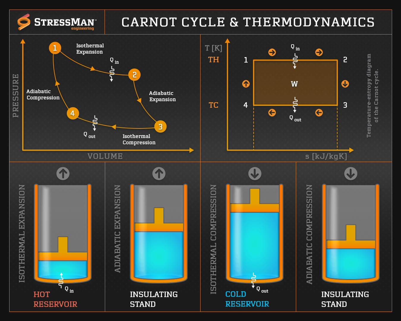
Let's focus on the P-V diagram in the image.
- Path 1 → 2 (Isothermal Expansion): Heat (or ) enters, work is done by the gas.
- Path 2 → 3 (Adiabatic Expansion): No heat transfer, work is done by the gas.
- Path 3 → 4 (Isothermal Compression): Heat (or ) leaves, work is done on the gas.
- Path 4 → 1 (Adiabatic Compression): No heat transfer, work is done on the gas.
The work done by the gas during expansion (the area under the top two curves) is greater than the work done on the gas during compression (the area under the bottom two curves). The difference between them is the net work () produced by the engine in one cycle. On the P-V diagram, this is the area enclosed by the loop. This is the payoff! It's the useful work we get out for the heat we put in.
Test your understanding!
A friend says, "I don't get it. In steps 3 and 4, you have to put work in to compress the gas. Doesn't that cancel out the work you got out in steps 1 and 2? Why does the engine produce any net work at all?"
In simple terms, explain to your friend why the work output is greater than the work input in a Carnot cycle. (Hint: Look at the P-V diagram and think about the pressures during expansion vs. compression.)
Show answer
That's a great question! The key is that the engine does its work at a higher pressure than when work is done on it.
Think about it like this:
- Expansion (Work Out): During the expansion phases (1→2 and 2→3), the gas is at a relatively high pressure. It's pushing the piston with a lot of force, so we get a lot of work out of it. This corresponds to the area under the top part of the loop.
- Compression (Work In): During the compression phases (3→4 and 4→1), the gas is at a relatively low pressure. We have to push the piston back in, but we're fighting against a weaker force. This requires less work. This corresponds to the area under the bottom part of the loop.
Because we get work out at high pressures and put work in at low pressures, the output is greater than the input. The difference is the net work we get, which is the area inside the loop on the P-V diagram.
Key Takeaways
Fantastic! We've successfully blueprinted the "perfect" engine.
- The Carnot Cycle is a theoretical, ideal engine cycle composed of four reversible processes.
- The four processes are:
- Reversible Isothermal Expansion (takes in heat at )
- Reversible Adiabatic Expansion (cools from to )
- Reversible Isothermal Compression (rejects heat at )
- Reversible Adiabatic Compression (heats from to )
- On a P-V diagram, the Carnot cycle forms a closed loop made of two isotherms and two steeper adiabats.
- The area enclosed by the loop represents the net work done by the engine per cycle.
Preview of the Next Lesson
We now know what the Carnot cycle is. The next logical question is, how good is it?
In our next lesson, we will build on this foundation to answer that question precisely. We will explain why the Carnot cycle is the most efficient cycle possible operating between two temperatures and derive the famous Carnot efficiency formula. This simple but powerful equation tells us the absolute maximum efficiency any heat engine can ever achieve, and it depends only on two numbers: and .