Hello! Welcome to the next lesson in your Embedded Interview Preparation Bootcamp.
In our last lesson, we mastered the modern gpiod_* framework, learning how to describe, acquire, and control GPIOs from a kernel driver. We ended on a key insight: a physical pin on an SoC is a shared resource. While it can be a GPIO, it can also be configured to serve as a UART transmitter, an I2C clock line, or part of an SPI bus.
This lesson addresses the fundamental question: how does the kernel manage this functional flexibility? We will explore the two critical frameworks that enable a device driver to claim pins for a specific purpose and provide them with the necessary clock signals to operate.
Your experience in automotive systems has given you a strong intuition for how hardware peripherals are initialized. In Linux, this process is formalized into powerful, board-agnostic frameworks that are a primary focus in senior-level interviews.
Your learning outcome for this lesson is to: Use the pinctrl and clock frameworks to configure pin multiplexing and manage peripheral clock rates.
1. From GPIO to Peripheral: The Role of Pin Control
Modern SoCs pack immense functionality into a limited number of physical pins. To accommodate this, most pins are multiplexed, meaning they can be electronically switched to serve different functions. The framework responsible for managing this is called pinctrl.
The pinctrl subsystem manages two distinct but related concepts:
- Pin Multiplexing (pinmux): Selecting the function of a pin or group of pins. For example, switching a pin from its default GPIO function to its "alternate function 2" to act as
UART1_TX. - Pin Configuration (pinconf): Setting the electrical properties of a pin, such as enabling an internal pull-up/pull-down resistor, setting its drive strength, or configuring it as open-drain.
Let's watch a short segment that uses a processor datasheet to visualize exactly what pin multiplexing means at the hardware register level.
Adding a LED to the Device Tree & Pin multiplexing
This video from Johannes 4GNU_Linux provides a clear, hardware-centric explanation of pin multiplexing by examining the datasheet for a Texas Instruments AM62x processor.
Watch the clip from 05:34 to 07:15. Notice how a 'Mux mode' register field is used to select the function for a physical pin, such as OSPI clock vs. GPIO. This is the low-level mechanism that the pinctrl framework abstracts.
As you saw, the pinctrl framework is the standardized Linux interface for manipulating these multiplexer and configuration registers. Its primary goal is to abstract these board-specific details out of the device driver and into the Device Tree.
2. Describing Pin Control in the Device Tree
The core principle is that a driver should not know which pins it's using, only that it needs a set of pins for a particular function (e.g., "my I2C bus"). The Device Tree is where we define this mapping.
This involves two parts:
- A
pinctrlnode that describes available pin groups and their functions. This is usually provided by the SoC vendor in a base.dtsifile. - Properties within a device's node that reference the required pin configurations from the
pinctrlnode.
A crucial concept here is states. A device typically has different pin requirements depending on its power state. The most common states are:
default: The configuration for normal operation.sleep: A low-power configuration, perhaps setting pins to high-impedance or a specific level to save power when the device is suspended.

The pinctrl framework's architecture reflects this separation of states, muxing, and configuration.
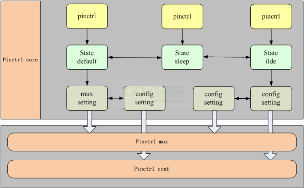
3. Using Pin Control from a Driver
The good news is that for the most common use case, the kernel does the heavy lifting for you. When your device driver's probe function is called, the core has likely already processed the pinctrl-0 = <&pinctrl_uart1_default>; line in your device tree and applied the default state.
However, you must understand how to manage these states for power management, which is a common interview topic.
PINCTRL (PIN CONTROL) subsystem
The official kernel documentation explains how drivers interact with the pinctrl framework, especially concerning power management states.
Read the sections titled 'Pin control requests from drivers' and 'PM interfaces'. Focus on understanding the roles of the standard states (default, init, sleep, idle) and the pinctrl_pm_select_* functions used in suspend/resume handlers.
Here's how a driver would typically manage this for suspend and resume:
static int my_uart_probe(struct platform_device *pdev)
{
    // The device core automatically selects the "default" pinctrl state
    // before probe is called. No manual action is needed here for basic setup.
    // ...
    return 0;
}


#ifdef CONFIG_PM_SLEEP
static int my_uart_suspend(struct device *dev)
{
    // Switch to the low-power pin configuration.
    return pinctrl_pm_select_sleep_state(dev);
}

static int my_uart_resume(struct device *dev)
{
    // Restore the pins for normal operation.
    return pinctrl_pm_select_default_state(dev);
}

static const struct dev_pm_ops my_uart_pm_ops = {
    .suspend = my_uart_suspend,
    .resume  = my_uart_resume,
};


#define DRIVER_PM_OPS (&my_uart_pm_ops)
#else
#define DRIVER_PM_OPS (NULL)
#endif

static struct platform_driver my_uart_driver = {
    .probe  = my_uart_probe,
    .driver = {
        .name  = "my-uart",
        .pm    = DRIVER_PM_OPS,
    },
};
This demonstrates the clean separation: the driver simply requests named states (default, sleep), and the pinctrl framework, guided by the device tree, handles the low-level register writes.
4. The Common Clock Framework (CCF)
Once the pins are correctly multiplexed, the peripheral needs a clock signal to function. The frequency of this clock is often critical (e.g., determining a UART's baud rate). The Common Clock Framework (CCF) is the standard kernel subsystem for managing the complex clock trees found in modern SoCs.
Like pinctrl, the CCF's philosophy is to describe the hardware relationships in the Device Tree and provide a generic API for drivers to use.
Describing Clocks in the Device Tree
A device declares its need for a clock using the clocks and clock-names properties.
clocks: A list of phandles pointing to the clock(s) it consumes.clock-names: A list of human-readable strings to identify each clock, allowing the driver to request a specific clock by name.
// In the SoC's .dtsi file, a clock controller is defined:
clock_controller: clock-controller@12340000 {
    compatible = "vendor,clock-controller";
    reg = <0x12340000 0x1000>;


    #clock-cells = <1>;
};

// In your board's .dts file, a device uses the clock:
uart1: serial@80001000 {
    compatible = "vendor,my-uart";
    reg = <0x80001000 0x100>;

    /* Pinctrl properties as discussed before */
    pinctrl-names = "default";
    pinctrl-0 = <&pinctrl_uart1_default>;

    /* Clock properties */
    clocks = <&clock_controller 15>, /* Points to the 15th clock from this controller */
             <&clock_controller 22>;
    clock-names = "peripheral_clk",  /* Name for the bus interface clock */
                  "core_clk";        /* Name for the baud rate generator clock */
};
Using Clocks from a Driver
A driver interacts with the CCF using a straightforward API. Let's explore the key functions through a well-structured presentation.
Common clock framework: how to use it
This presentation from Bootlin provides an excellent overview of the Common Clock Framework, focusing on how device drivers consume clocks.
Please review slides 23 through 38. Focus on: Slides 25 & 37: How clocks are declared and referenced in the Device Tree. Slides 36 & 38: The driver-side API, showing devm_clk_get, clk_prepare_enable, and clk_get_rate. This is the most critical part for a driver developer.
The typical workflow in a driver's probe function is:
- Get a handle to the clock using
devm_clk_get(). This is the device-managed version that handles cleanup automatically. - Enable the clock using
clk_prepare_enable(). This is a crucial step. It recursively prepares and enables the entire clock path leading to your peripheral. - (Optional) Get the rate using
clk_get_rate()if your driver needs to perform calculations, like setting a baud rate divisor. - (Optional) Set the rate using
clk_set_rate()if your hardware and the clock tree support dynamic frequency scaling.
Here's a practical example for our UART driver:
#include <linux/clk.h>

static int my_uart_probe(struct platform_device *pdev)
{
    struct device *dev = &pdev->dev;
    struct clk *core_clk;
    unsigned long baud_rate_hz;
    int ret;

    // Get a handle to the clock named "core_clk" from the DT
    core_clk = devm_clk_get(dev, "core_clk");
    if (IS_ERR(core_clk)) {
        dev_err(dev, "Failed to get core clock\n");
        return PTR_ERR(core_clk);
    }

    // Prepare and enable the clock and its parents.
    ret = clk_prepare_enable(core_clk);
    if (ret) {
        dev_err(dev, "Failed to enable core clock\n");
        return ret;
    }

    // Now the clock is running. We can get its frequency.
    baud_rate_hz = clk_get_rate(core_clk);
    if (baud_rate_hz == 0) {
        dev_err(dev, "Core clock has zero rate\n");
        clk_disable_unprepare(core_clk); // Clean up
        return -EINVAL;
    }

    // Use baud_rate_hz to calculate and set the UART's divisor register...
    // ...

    // At driver removal, the clock must be disabled.
    // devm_clk_get automatically registers a cleanup function that calls
    // clk_disable_unprepare(core_clk), so manual cleanup is often not needed.

    return 0;
}
A key detail is the separation of prepare and enable. clk_prepare() can sleep (e.g., waiting for a PLL to lock), while clk_enable() is atomic and just flips a gate bit. clk_prepare_enable() conveniently combines both.
5. Interview Perspective
Understanding pinctrl and CCF is a hallmark of an experienced embedded Linux engineer. You're demonstrating that you understand modern kernel design principles, not just how to poke registers.
-
Question: "You're bringing up a new I2C device on a custom board. It's not working. You've confirmed the driver is probing. What are the first two things you check in the Device Tree?"
- Your Answer: "The first two things I'd verify are the
pinctrlandclockconfigurations for that I2C controller. I'd check that thepinctrl-0property correctly points to the pin group for the I2C SCL/SDA lines and that theclocksproperty correctly references the peripheral clock for the I2C block. An incorrect pinmux or a gated clock are the most common reasons for a peripheral to be unresponsive."
- Your Answer: "The first two things I'd verify are the
-
Question: "What is the difference between
clk_prepare()andclk_enable(), and why are they separate operations?"- Your Answer: "
clk_prepare()readies a clock source and all its parents, which might involve slow operations like powering up a PLL. Because of this, it's allowed to sleep and must be called from a process context.clk_enable()simply un-gates a clock that is already prepared. This is a fast, atomic operation that can be called from contexts where sleeping is not allowed. The separation allows for performance-critical code to quickly gate and un-gate clocks without the overhead of preparing them each time."
- Your Answer: "
-
Question: "How would you configure a UART's pins to enter a low-power state during system suspend?"
- Your Answer: "This is done using
pinctrlstates. In the device tree, I'd define asleepstate for the UART's pin group, for example,pinctrl-1 = <&pinctrl_uart1_sleep>;. This state would configure the pins for low-power (e.g., high-impedance). The driver'ssuspendhandler in itsdev_pm_opsstructure would then callpinctrl_pm_select_sleep_state(dev). On resume, it would callpinctrl_pm_select_default_state(dev)to restore normal operation."
- Your Answer: "This is done using
Conclusion
You have now connected the dots between a physical pin and a fully functional peripheral. By mastering the pinctrl and clock frameworks, you move from board-specific register programming to writing portable, robust, and power-aware device drivers that adhere to modern Linux kernel standards.
Key Takeaways:
- Hardware configuration belongs in the Device Tree. Drivers should be generic.
- The
pinctrlframework manages a pin's function (pinmux) and electrical properties (pinconf) through named states likedefaultandsleep. - The Common Clock Framework (CCF) manages the clock tree, allowing drivers to enable, disable, and query the rate of the clocks their peripherals depend on.
- For a driver, the flow is simple: the kernel applies the
defaultpinctrlstate, and the driver usesdevm_clk_getandclk_prepare_enableto activate its clock.
Preview of the Next Lesson:
With our device's pins and clocks fully configured, we're ready to make it communicate with the outside world. The next step is to implement the standard user-space interface. In the next lesson, we will implement a basic character device driver, including read, write, and ioctl handlers, using copy_from_user/copy_to_user for safe data transfer. This is the bridge between your kernel driver and user-space applications.