Introduction
In our last lesson on LFOs, we observed a fascinating phenomenon: when a modulating oscillator's frequency crosses the threshold of human hearing (around 20 Hz), it ceases to produce a simple vibrato and instead begins to generate a fundamentally new, complex timbre. This is the gateway to Frequency Modulation (FM) synthesis, a technique discovered by John Chowning at Stanford in the 1960s that revolutionized electronic music.
This lesson delves into the principles of FM synthesis. We will move beyond the intuitive "wobble" of LFOs to a more rigorous, mathematical understanding of how two simple sine waves can interact to create sounds of extraordinary harmonic richness. Your background in wave mechanics and Fourier analysis will be particularly valuable here, as we will explore how the relationship between a carrier and a modulator oscillator dictates the resulting sound's harmonic structure. Our goal is to understand how to control this process, relating the crucial parameters of the modulation index and the carrier-to-modulator ratio to the harmonic complexity of the final sound.
The Mathematical Heart of FM
At its core, FM synthesis involves two oscillators.
- The Carrier () is the primary oscillator. If it were unmodulated, it would produce a simple sine tone at its set frequency, which determines the sound's perceived pitch.
- The Modulator () is a second oscillator, also at audio rate, whose output is not heard directly. Instead, it dynamically changes the frequency of the carrier.
The instantaneous frequency of the carrier, , is therefore not constant. It is the sum of its base frequency and the output of the modulator:
Here, is the carrier frequency, is the modulator frequency, and is the peak frequency deviation, which corresponds to the modulator's amplitude.
A crucial point, which your physics background will make intuitive, is that frequency is the time derivative of phase (). Therefore, to find the carrier's signal over time, we cannot simply plug into a sine function. We must integrate the instantaneous frequency to find the phase, , which then becomes the argument of the carrier's sine function.
FM Synthesis Explained For Audio Programmers: Art and Science
This article provides an excellent mathematical foundation for FM synthesis, tailored for a technical audience.
Please read the first part of the article, from the beginning down to the diagram in the section "Simple FM Diagram". Focus on the derivation of the proper FM formula (Equation 5), which involves integrating the instantaneous frequency to find the phase. Note the distinction between the incorrect, naive approach (Equation 2) and the correct one.
As the reading mentions, many digital synthesizers, including the iconic Yamaha DX7, actually implement a slightly different but closely related method called Phase Modulation (PM). From a practical sound design perspective, the audible results and control parameters are so similar that the term "FM synthesis" is used universally to describe both.
Sidebands: The Source of Timbral Richness
When the modulator's frequency is in the audio range, our ears no longer perceive a simple pitch "wobble." Instead, the modulation process creates new frequency components that did not exist in either the carrier or the modulator. These are called sidebands.
Let's watch a demonstration of this transformation.
Understanding FM #2 - The magic of sidebands and the origin of all those cool sounds
This video from the "Understanding FM" series by Sound + Voltage provides a clear, practical demonstration of how sidebands emerge.
Watch from the start of the FM demonstration. Notice how as the modulator's rate increases from a slow LFO into the audio range, the sound changes from a siren-like sweep into a complex, static tone with new frequency components appearing on the spectrum analyzer. Then, watch the next experiment from the 880Hz test, which reinforces how more sidebands appear as the modulation amount increases.
The frequencies of these sidebands are not random. They appear symmetrically above and below the carrier frequency at integer multiples of the modulator's frequency. The formula for the frequencies of all partials in the resulting spectrum is:
When , we have the carrier frequency itself. When , we have the first pair of sidebands at and . When , we get a second pair at and , and so on.
A fascinating phenomenon occurs with "negative frequencies." If a sideband calculation results in a negative value (e.g., Hz, Hz, giving a lower sideband of -100 Hz), that frequency is "reflected" back from 0 Hz into the positive spectrum as a component at its absolute value (100 Hz), but with its phase inverted. This is a key source of the complex and sometimes surprising timbres of FM.
Controlling the Spectrum: Index and Ratio
We have two primary levers for sculpting the FM spectrum: the Modulation Index, which controls brightness and the number of sidebands, and the Carrier-to-Modulator Ratio, which controls harmonicity.
1. The Modulation Index ()
The Modulation Index is a dimensionless quantity that represents the intensity of the modulation. It is defined as the ratio of the peak frequency deviation () to the modulator frequency ():
In simpler terms, the index controls the bandwidth and brightness of the sound.
- A low index () results in a spectrum with only a few significant sidebands, concentrated around the carrier. The sound is simple, often close to a pure sine wave.
- A high index () pushes energy out to many more sideband pairs, creating a wide, complex, and bright spectrum.

The amplitudes of the carrier and each sideband are determined by a family of mathematical functions you may have encountered in physics: Bessel functions of the first kind, denoted . The amplitude of the k-th sideband pair is proportional to , and the carrier's amplitude is proportional to .
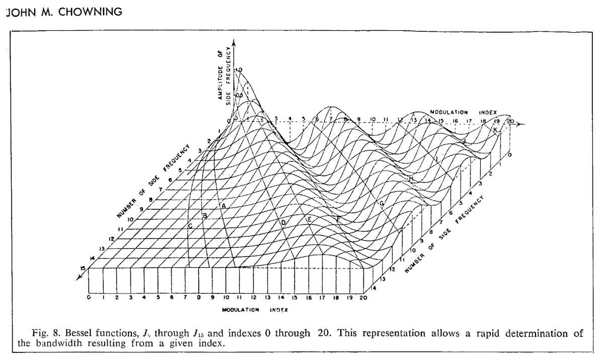
Studying this plot reveals a key characteristic of FM: for specific values of the index, certain Bessel functions cross zero. This means that at particular modulation depths, the carrier frequency itself can vanish completely (), or specific sideband pairs can disappear, creating dynamic changes in the timbre.
FM Synthesis Explained For Audio Programmers: Art and Science
Let's return to the "FM Synthesis Explained" article to solidify our understanding of the Modulation Index and its relationship to the spectrum.
First, read the section "Modulation Index" to see why it's a more consistent parameter for timbre control than raw modulator amplitude. Then, read the sections "How to control brightness" and "Bessel functions". These sections directly connect the index I to the perceived brightness and the underlying Bessel function mathematics.
2. The Carrier-to-Modulator Ratio (C:M)
While the index controls the "how much," the C:M ratio () controls the "what." It determines the fundamental character and harmonicity of the sound.
-
Harmonic Spectra (Rational Ratios): If the C:M ratio is a simple fraction of small integers (e.g., 1:1, 1:2, 2:1, 3:2), the resulting sidebands will align to form a harmonic series. The perceived pitch, or fundamental frequency (), will be the greatest common divisor of the carrier and modulator frequencies. For instance, if Hz and Hz, the ratio is 3:2, and the fundamental will be 100 Hz. The sound will have a clear, identifiable pitch.
-
Inharmonic Spectra (Irrational Ratios): If the C:M ratio is an irrational number (e.g., ) or a ratio of large, coprime integers (e.g., 23:31), the sidebands will not align into a harmonic series. This results in an inharmonic spectrum, characteristic of bells, gongs, and metallic or noisy textures—perfect for the industrial and experimental genres you're interested in.
Let's watch a video that brilliantly explains and demonstrates how the C:M ratio works.
Understanding FM #4 - Virtual tones and how sidebands become harmonics
This "Understanding FM" video focuses entirely on the C:M ratio and its consequences for the resulting sound.
This is a crucial resource. Please watch from "virtual tones", where the presenter introduces the idea that the greatest common factor of f_C and f_M becomes the fundamental frequency of a harmonic tone. Then, continue from the inharmonic example to see what happens when the frequencies share no common factor. Finally, watch the most important segment from the ratio explanation, which breaks down what the two numbers in the simplified C:M ratio tell you about the resulting harmonic series.
As the video explains, once you find the fundamental frequency () by taking the greatest common divisor, you can simplify the ratio to where and . These two integers give you powerful predictive control:
- M determines the density of the harmonic series. If M=1, all harmonics are present. If M=2, only every second harmonic (the odd ones) will be present. If M=3, every third harmonic will be missing, and so on.
- C determines where the carrier frequency is located within that harmonic series. If C=1, the carrier is the fundamental (or an octave of it). If C is large, the carrier is a high harmonic, and a higher modulation index will be needed to generate the lower harmonics and establish the perceived pitch.
Conclusion
Frequency Modulation is a synthesis method where complexity emerges from simple rules. By starting with just two sine waves, we can generate an immense palette of sounds, from warm and pitched to cold, metallic, and noisy. This is achieved not by filtering, but by generating new harmonic content from the outset.
Key Takeaways:
- FM synthesis uses an audio-rate modulator oscillator to alter the frequency of a carrier oscillator.
- This process creates new frequencies called sidebands located at .
- The Modulation Index () controls the spectral complexity and brightness. Higher indices lead to more sidebands and wider bandwidth, with amplitudes determined by Bessel functions.
- The Carrier-to-Modulator Ratio (C:M) controls the harmonicity of the spectrum. Simple integer ratios produce harmonic, pitched sounds, while irrational or complex ratios produce inharmonic, metallic, or bell-like sounds.
- For harmonic sounds, the perceived fundamental frequency is the greatest common divisor of the carrier and modulator frequencies.
In the next lesson, we will apply these principles in a practical context. We will learn how to design specific types of sounds—a punchy percussive hit and a rich, evolving pad—by combining our knowledge of FM with the envelopes and filters we've previously studied.