Welcome to your next lesson. In our previous session, we explored kinematics, describing the geometry of joint motion through concepts like arthrokinematics and axes of rotation. We focused on how the body moves. Today, we transition to kinetics, the study of why the body moves, by analyzing the forces and torques involved.
This lesson is designed to help you apply the principles of levers, force couples, and torque to analyze human movement. Mastering these fundamental biomechanical concepts is not just crucial for your MPT entrance exams; it's the foundation for understanding musculoskeletal pathology, designing therapeutic exercises, and performing manual assessments. We'll break down these principles and see how they are applied in clinical contexts.
1. The Body as a System of Levers
At its core, much of human movement can be understood by modeling bones, joints, and muscles as a system of levers. A lever is a simple machine consisting of a rigid bar (a bone) that pivots around a fixed point called a fulcrum (a joint). An effort force (from muscle contraction) is applied to the lever to move a resistance or load (such as body weight or an external object).
Levers are categorized into three classes based on the relative positions of the fulcrum, effort, and resistance. A great way to remember this is with the mnemonic FRE—for Fulcrum, Resistance, Effort—to recall which component is in the middle for classes 1, 2, and 3, respectively.
The following video provides an excellent overview of the three lever classes and how to identify them in the human body.
LEVER SYSTEM PART 1 (basic concepts of biomechanics) Physiotherapy class
This video from the "Movement Science" channel clearly explains the lever systems with helpful mnemonics and anatomical examples.
Please watch the following segments: First, understand the core mnemonic from this introduction. Next, see how a first-class lever operates, using the skull and shoulder as examples. Then, watch the explanation of a second-class lever with the foot and brachioradialis examples. Finally, learn about the most common type, the third-class lever, using the biceps and quadriceps. The final summary provides a great recap.
To consolidate what you've just watched, let's formally define the three classes with the aid of the image below.

- First-Class Lever: The fulcrum is between the effort and resistance (e.g., a seesaw). Example: The head balancing on the atlanto-occipital joint. The posterior neck muscles (effort) counteract the weight of the head (resistance).
- Second-Class Lever: The resistance is between the fulcrum and the effort. Example: Standing on your tiptoes. The ball of the foot is the fulcrum, body weight is the resistance, and the calf muscles provide the effort. This class is built for power.
- Third-Class Lever: The effort is between the fulcrum and the resistance. This is the most common type of lever in the human body. Example: Biceps curl. The elbow is the fulcrum, the biceps provides the effort, and the weight in your hand is the resistance. This class is built for speed and range of motion.
Mechanical Advantage
A crucial concept related to levers is mechanical advantage (MA). It quantifies the efficiency of the lever system.
Levers in the Musculoskeletal System: Types, Mechanics, and Applications | Notes
This guide from Pearson provides a concise explanation of mechanical advantage and the functional trade-offs of different lever classes.
Please read the sections on Mechanical Advantage (MA) and The Trade-Off. The summary table is also an excellent revision tool.
As the text explains, mechanical advantage is the ratio of the effort's moment arm to the resistance's moment arm.
- MA > 1 (Second-Class Levers): The effort force required is less than the resistance force. These levers are force multipliers.
- MA < 1 (Third-Class Levers): The effort force required is greater than the resistance force. This may seem inefficient, but the trade-off is that a small muscle contraction can produce a large, rapid movement at the end of the limb. This is why most of our limbs are designed this way—to favor speed and range of motion over raw power.
2. Torque: The Force of Rotation
Forces cause linear motion (translation), but in the human body, muscles typically cause rotation around joints. The rotational equivalent of a force is torque (or moment).
Torque = Force × Moment Arm
The moment arm is the perpendicular distance from the axis of rotation (the fulcrum) to the line of action of the force. This "perpendicular distance" is the most critical part of the definition.
In any static situation (like holding a weight steady), the joint is in equilibrium. This means the internal torque generated by the muscles must be equal and opposite to the external torque generated by the load.
Internal Torque = External Torque
To analyze these forces and torques accurately, we use free-body diagrams. These diagrams isolate a body segment and illustrate all the forces acting upon it. The image below shows a classic example for the forearm.
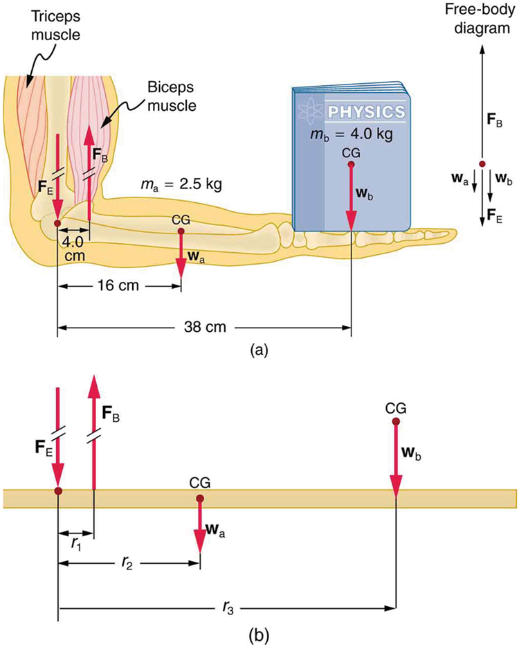
To delve deeper into the analysis, the following reading breaks down how to calculate forces and torques.
Biomechanical Principles - Clinical GateClinical Gate
This chapter excerpt from Clinical Gate provides a detailed guide to analyzing forces and torques in a clinical context.
Please review the following sections: Start under the heading Free Body Diagram. Read the introduction and the five steps. This formalizes the process of creating diagrams like the one shown above. Next, read the section Contrasting Forces and Torques. This explains how to resolve internal (muscle) and external (gravity/load) forces into components and how joint angle changes the torque. Finally, read Comparing Two Methods to understand the two equivalent ways to calculate torque.
The key takeaway is that muscle forces are typically much larger than the loads they are moving because their internal moment arms are very short. This has significant clinical implications for joint compression and stability.
3. Force Couples: Synergistic Rotation
While we often simplify muscle action to a single force vector, movement is rarely that simple. Often, two or more muscles pull in different, sometimes opposing, directions to create a single, pure rotation or to stabilize a joint. This is known as a force couple.
The rotator cuff of the shoulder provides a classic and clinically vital example of a force couple in action.
The Rotator Cuff Force Couples
This video from "Muscle & Motion" uses outstanding animations to illustrate the force couples of the rotator cuff.
Watch the entire video to understand how these muscles work in harmony. Pay special attention to: The deltoid-rotator cuff force couple, where the downward pull of the infraspinatus, teres minor, and subscapularis counteracts the deltoid's superior pull to keep the humeral head centered during abduction. The anterior-posterior force couple, where the subscapularis (anteriorly) and the infraspinatus/teres minor (posteriorly) co-contract to stabilize the "ball" in the "socket."
Understanding force couples is essential for rehabilitation. An imbalance in a force couple, where one muscle is weak or overactive, leads to abnormal joint mechanics (like the humeral head riding up during abduction), which is a common cause of shoulder impingement syndrome.
Conclusion
In this lesson, we have moved from describing motion to analyzing its causes. We've seen how the musculoskeletal system functions as a series of levers, translated the forces involved into torques that produce rotation, and appreciated the sophisticated coordination of force couples.
Key Takeaways for Your Exam Revision:
- Lever Classes (FRE): Be able to identify the class of a lever based on the arrangement of Fulcrum, Resistance, and Effort. Know the MA and functional trade-off for each. (Most are 3rd class: MA < 1, favors speed/ROM).
- Torque: Defined as Force × Perpendicular Moment Arm. In static equilibrium, Internal Torque = External Torque.
- Mechanical Disadvantage: Muscles operate at a significant mechanical disadvantage (short IMA vs. long EMA), meaning they must generate very large forces, which leads to high joint compression forces.
- Force Couples: Muscles work synergistically, often pulling in different directions, to create clean rotation and dynamic stability (e.g., the rotator cuff stabilizing the glenohumeral joint).
- Free-Body Diagrams: They are the essential first step in solving any biomechanics problem.
The "Biomechanical Principles" resource you read contains several fully worked-out problems in the section INTRODUCTION TO BIOMECHANICS: FINDING THE SOLUTIONS. Reviewing these will be excellent practice for applying these principles to exam-style questions.
In our next lesson, we will apply these kinetic principles to a specific and complex area: the biomechanics of the spinal column. We will analyze the forces acting on the vertebrae and intervertebral discs during various activities.