Hello! Welcome back to our course on professional embedded systems development.
In the last lesson, we took a high-level tour of your STM32 microcontroller's internals. You learned about the ARM Cortex-M3 core, the system memory map, and the crucial concept of Memory-Mapped I/O. You now know that controlling hardware is a matter of reading from and writing to specific memory addresses, and you know how to use the reference manual to find them.
This lesson bridges the gap between knowing where the registers are and knowing how to manipulate them correctly using the C language. We will focus on this learning outcome: Apply 'volatile', fixed-width integers, and bitwise operators for direct register manipulation. These three C language features are the absolute bedrock of bare-metal firmware development. Mastering them is non-negotiable for any professional embedded engineer.
By the end of this lesson, you will understand:
- Why standard C integer types can be problematic and how to ensure your code is predictable.
- How to prevent the C compiler from breaking your hardware-interacting code.
- The essential C operators used to "flip the switches" inside microcontroller registers.
Let's begin by addressing the first requirement for predictable code: data types.
1. Ensuring Predictability with Fixed-Width Integers
In the previous lesson, we saw that memory-mapped registers are 32 bits wide on our STM32. It seems logical to use a C type like int or unsigned int to represent them. However, this contains a hidden trap. The C standard does not guarantee the size of types like int. On a 32-bit ARM processor, an int is 32 bits. But on an older 16-bit or 8-bit microcontroller, it might be 16 bits. Writing code that relies on int being 32 bits is not portable and can lead to subtle bugs.
To solve this, the C99 standard introduced a header file that is indispensable in embedded programming: <stdint.h>.
#11 Standard integers (stdint.h) and mixing integer types
This video from Quantum Leaps, LLC explains why standard C integer types are ambiguous and introduces the standard solution, stdint.h.
Please watch from 00:59 to 06:30. Focus on understanding the problem with built-in types and how stdint.h provides a portable and unambiguous solution.
As the video explains, <stdint.h> provides a set of integer types with guaranteed sizes. The most common ones you will use are:
uint8_t: unsigned 8-bit integer (0 to 255)uint16_t: unsigned 16-bit integer (0 to 65,535)uint32_t: unsigned 32-bit integer (0 to 4,294,967,295)int8_t,int16_t,int32_t: their signed counterparts.
From this point forward in our course, we will exclusively use these fixed-width types. When we declare a pointer to a 32-bit hardware register, we will always use uint32_t. This ensures our code's intent is clear and its behavior is identical regardless of the compiler or underlying architecture.
2. Preventing Compiler Errors with the volatile Keyword
The next challenge comes from an unlikely source: the compiler's optimization features. Compilers are designed to make your code smaller and faster by eliminating redundant operations. Consider this pseudo-code:
// Wait for a hardware status flag at a specific address to become 1
uint32_t* status_register = (uint32_t*) 0x40001000;
while (*status_register == 0) {
    // Do nothing, just wait
}
// Proceed...
A smart compiler might look at this and think: "The value at *status_register is never changed within the loop. Therefore, I can optimize this by reading the value just once before the loop. If it's 0, this is an infinite loop." The compiler would be wrong, because the value at that memory address can be changed by the hardware itself, completely outside the program's control.
To prevent this incorrect optimization, we use the volatile keyword.
C Bare Metal Programming on STM32F103 — Booting up
The article 'C Bare Metal Programming on STM32F103' provides a clear, practical explanation of why volatile is necessary when dealing with peripheral registers.
Read the part of the text that begins with the paragraph 'To avoid writing directly arbitrary numerical values in our code...'. Focus on the explanation of the volatile keyword and how it is used when defining a pointer to a register.
The volatile keyword is a directive to the compiler that says: "The value of this variable can change at any time. Never make assumptions about its value, and never optimize away any reads from or writes to it."
When defining a pointer to a memory-mapped register, we declare the pointer to point to volatile data. The correct syntax is:
volatile uint32_t* my_register_pointer;
This tells the compiler that the 32-bit unsigned integer at the address pointed to is volatile. This is the standard and correct way to access hardware registers in C.
3. The Toolkit for Register Control: Bitwise Operators
We now know how to define a safe and portable pointer to a 32-bit register. The final step is to learn how to manipulate the individual bits within that register. This is done using C's bitwise operators.
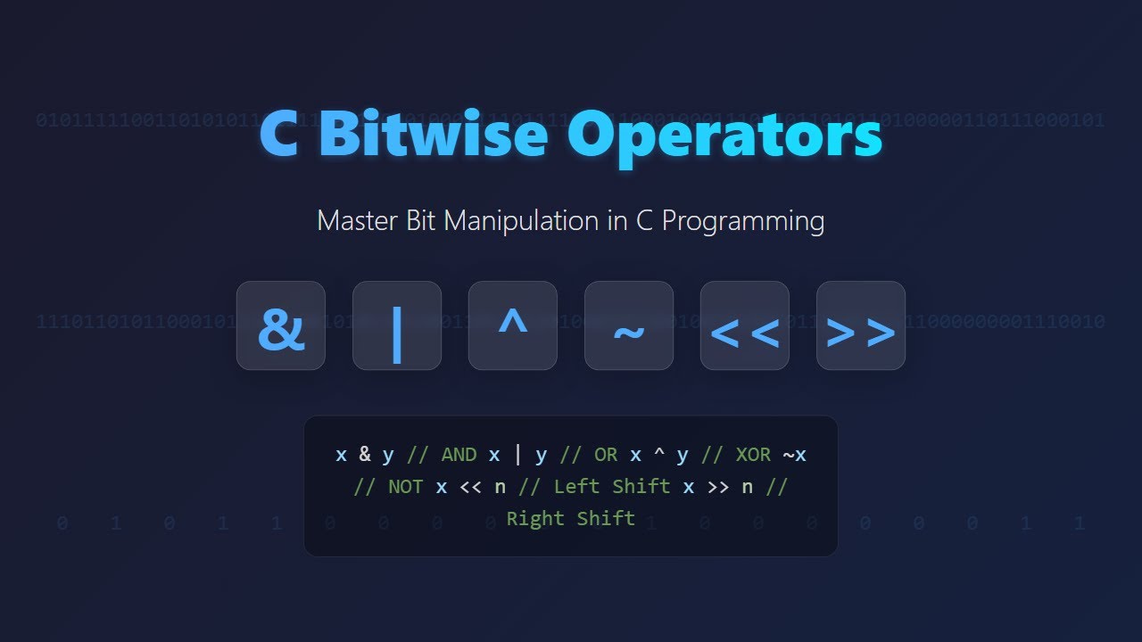
A 32-bit register is like a panel with 32 individual switches, labeled from bit 0 to bit 31. Bitwise operators allow us to flip these switches individually or in groups, without disturbing the others.
STM32 #8: Binary, Bitwise Operators, Flags, and Register ...
This article from skoopsy.dev is an excellent and thorough guide to bitwise operations and their direct application in embedded C programming.
Please read the following sections: 'Bit wise operators', 'Enabling Flags', 'Resetting bits (Disabling flags)', 'Macros', and 'Now it’s actually starting to look like embedded…'. This will give you a complete toolkit for manipulating registers.
Let's summarize the key techniques from the article for manipulating a register REG:
Setting a Bit (or bits)
To set a bit to 1, we use the bitwise OR (|) operator. The standard idiom is REG |= (1U << BIT_POSITION);.
(1U << BIT_POSITION)creates a mask with a single '1' at the desired bit position.Udenotesunsigned.- The
|=operation merges this mask with the register's current value. Any bit that was already 1 stays 1, and the bit at our target position becomes 1. All other bits are unaffected.
Example: To set bit 4 of RCC_APB2ENR to enable the clock for GPIO Port C:RCC_APB2ENR |= (1U << 4);
Clearing a Bit (or bits)
To clear a bit to 0, we use the bitwise AND (&) operator combined with the bitwise NOT (~) operator. The idiom is REG &= ~(1U << BIT_POSITION);.
(1U << BIT_POSITION)creates the same mask as before (e.g.,00010000).~inverts this mask to11101111.- The
&=operation uses this inverted mask to force the bit at the target position to 0, while leaving all other bits unchanged (sincebit & 1isbit).
Example: To clear bit 4 of RCC_APB2ENR:RCC_APB2ENR &= ~(1U << 4);
Toggling a Bit
To flip a bit from 0 to 1 or 1 to 0, we use the bitwise XOR (^) operator. The idiom is REG ^= (1U << BIT_POSITION);. This is very useful for tasks like blinking an LED.
Example: To toggle bit 13 of GPIOC_ODR (Output Data Register):GPIOC_ODR ^= (1U << 13);
Checking a Bit
To check if a bit is set, we use the bitwise AND (&) operator to mask out the single bit we care about.
Example: To check if the clock for GPIO Port C (bit 4) is enabled:if (RCC_APB2ENR & (1U << 4)) { /* Bit is set */ }
Test your understanding!
Let's say you have a register defined as volatile uint32_t* MY_REGISTER; and its current value is 0x0000F00D (binary ...1111 0000 0000 1101).
Write a single line of C code for each of the following operations:
- Set bit 5 to 1.
- Clear bit 12 to 0.
- Check if bit 3 is set (the expression should evaluate to true).
- Clear bits 8, 9, 10, and 11 simultaneously.
Show answer
- Set bit 5:
*MY_REGISTER |= (1U << 5);
The new value will be0x0000F02D. - Clear bit 12:
*MY_REGISTER &= ~(1U << 12);
The original value has bit 12 set (Fis1111). This operation will change it.0x0000F00Dbecomes0x0000E00D. - Check bit 3:
if (*MY_REGISTER & (1U << 3))
Bit 3 is set in...1101, so the result of the&operation will be non-zero, and the condition is true. - Clear bits 8-11:
*MY_REGISTER &= ~(0xFU << 8);
0xFis1111in binary.(0xFU << 8)creates the mask0x00000F00.~inverts it to0xFFFFF0FF. ANDing with this mask clears the four target bits.0x0000F00Dbecomes0x0000000D.
4. Application: Manipulating a GPIO Register
Let's put all three concepts together to perform a real hardware operation: configuring a GPIO pin. From the reference manual, we know that to configure pin 13 of Port C as a general-purpose output, we need to modify the GPIOC_CRH register (Port Configuration Register High).

Let's follow the steps described in the resources to do this with direct register access.
-
Define Register Addresses: We create macros for the base addresses and offsets.
#include <stdint.h>

// RCC base address from memory map
#define RCC_BASE              0x40021000
// GPIO Port C base address from memory map
#define GPIOC_BASE            0x40011000

// Pointer to the RCC APB2 Enable Register (Offset 0x18)
#define RCC_APB2ENR           (*(volatile uint32_t *)(RCC_BASE + 0x18))

// Pointer to the GPIOC Configuration Register High (Offset 0x04)
#define GPIOC_CRH             (*(volatile uint32_t *)(GPIOC_BASE + 0x04))
Notice the use of
volatile uint32_t *to create the pointers. -
Enable Peripheral Clock: First, we must enable the clock for Port C. This is done by setting the
IOPCENbit (bit 4) in theRCC_APB2ENRregister.// Enable clock for GPIO Port C RCC_APB2ENR |= (1U << 4); -
Configure Pin Mode: To set PC13 as an output, we need to write
0010(MODE = '10' for 2MHz output, CNF = '00' for push-pull) to its 4-bit field (bits 20-23). The safest way is the "clear-then-set" pattern.// 1. Clear the 4 bits for PC13 (bits 20, 21, 22, 23) // Mask is 0xF (binary 1111) shifted to the correct position GPIOC_CRH &= ~(0xFU << 20); // 2. Set the desired configuration (0x2 is binary 0010) GPIOC_CRH |= (0x2U << 20);
This sequence—defining a volatile pointer, enabling the clock, and then using bitwise operations to configure registers—is the fundamental workflow of bare-metal embedded programming.
Conclusion
In this lesson, you have acquired the essential C language toolkit for controlling microcontroller hardware at the lowest level. These concepts are not just academic; they are the daily tools of a firmware engineer.
Key Takeaways:
- Always use fixed-width integers from
<stdint.h>(e.g.,uint32_t) for hardware registers to ensure your code is portable and predictable. - Always use the
volatilekeyword when defining pointers to memory-mapped I/O to prevent the compiler from making incorrect optimizations. - Bitwise operators (
|,&,~,^,<<) are your primary tools for setting, clearing, toggling, and checking individual bits within a register. - The standard pattern for configuring a multi-bit field is to first clear the bits with
&= ~maskand then set the new value with|= value.
Preview of the Next Lesson:
We have now assembled all the foundational pieces: setting up the toolchain, understanding the memory map, and learning the C techniques for register manipulation. In the next lesson, we will finally combine all this knowledge to write, compile, and flash our first complete bare-metal program: the classic "Hello, World!" of embedded systems, blinking an LED.