Hello! Welcome to the next lesson in our journey to master bare-metal embedded programming.
In our last session, you mastered the essential C language tools for direct hardware control: volatile to prevent unwanted compiler optimizations, fixed-width integers from <stdint.h> for portable code, and the suite of bitwise operators for precise register manipulation.
Today, we put all that theory into practice. Our goal is to achieve this learning outcome: Write a bare-metal program to blink an LED by manipulating GPIO registers directly. This is the quintessential "Hello, World!" of the embedded world. You will write a complete C program from scratch that prepares the hardware and controls it to produce a visible result. This lesson synthesizes everything you've learned so far into a single, functional piece of firmware.
Let's get started.
1. Identifying Our Target: The Onboard LED
Before writing any code, we must know what we're controlling. Your STM32F103C8T6 "Blue Pill" board has a built-in LED that we can use for this exercise, so you don't need to wire anything externally yet. We just need to identify which pin it's connected to.
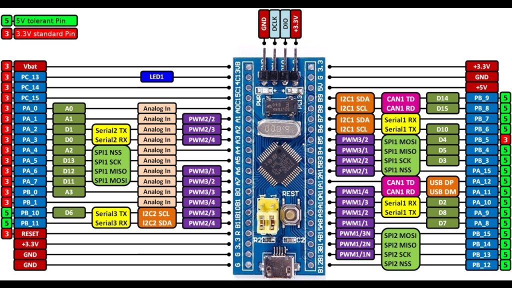
As you can see from the diagram, the onboard LED is connected to pin PC13, which means pin 13 of GPIO Port C.
An important real-world detail: this LED is configured as active-low. This means:
- Driving the PC13 pin LOW (0V) will turn the LED ON.
- Driving the PC13 pin HIGH (3.3V) will turn the LED OFF.
Keep this in mind as we write the code to control it.
2. The Bare-Metal GPIO Workflow
Controlling a peripheral on a microcontroller like the STM32 almost always follows a three-step process. For our GPIO pin, the steps are:
- Enable the Peripheral Clock: By default, all peripherals are disabled to save power. We must first enable the clock for GPIO Port C in the Reset and Clock Control (RCC) peripheral.
- Configure the GPIO Pin: We need to tell the pin to act as an output. This is done by writing specific values to the GPIO Port C configuration registers.
- Control the Output State: Once configured, we can turn the LED on and off by writing to the GPIO Port C data register.
Let's see this entire process in action before we write the code ourselves.
#1.2 STM32F103 Clock Setup using REGISTERS || TIMER Config || GPIO Config
This video from ControllersTech provides a clear demonstration of the register-level configuration required to blink the LED on a Blue Pill.
Watch from 11:18 to 16:23. The video walks through the same three steps we just discussed: enabling the GPIOC clock, configuring pin PC13, and then setting/resetting the pin inside the main loop to make it blink.
3. Writing the Blink Program Step-by-Step
Now, let's write our own version of this program. We will build the main.c file piece by piece, reinforcing the concepts from the previous lesson. The following article provides an excellent, detailed walkthrough of this exact process.
C Bare Metal Programming on STM32F103 — Booting up
This guide from Mattia Maldini is a masterclass in building a bare-metal application from the ground up. We will use it as our primary reference for writing the code.
Please read the sections titled 'Peripherals', 'Controlling a GPIO', and examine the final code block under the line 'The end result for main.c should look something like this:'. Pay close attention to how the author defines register addresses and uses bitwise operations.
Inspired by the guide, let's construct our code.
Part 1: Includes and Address Definitions
First, we create our main.c file. At the top, we include <stdint.h> for our fixed-width types and use #define to create symbolic names for all the memory addresses and bit values we'll need. This makes the code far more readable and maintainable.
#include <stdint.h>

// Memory base addresses from the reference manual memory map
#define RCC_BASE              0x40021000UL
#define GPIOC_BASE            0x40011000UL

// RCC register, offset 0x18 from RCC_BASE
#define RCC_APB2ENR           (*(volatile uint32_t *)(RCC_BASE + 0x18))

// GPIOC registers, offsets from GPIOC_BASE
#define GPIOC_CRH             (*(volatile uint32_t *)(GPIOC_BASE + 0x04))
#define GPIOC_ODR             (*(volatile uint32_t *)(GPIOC_BASE + 0x0C))

// Bit position for enabling the GPIOC clock in RCC_APB2ENR
#define RCC_IOPCEN            (1U << 4)

// The main function, where execution begins
int main(void) {
    // Our code will go here
}
Note the use of volatile uint32_t * to create our register pointers, exactly as we learned in the previous lesson.
Part 2: The main Function Logic
Now we fill in the main function with our three-step workflow.
Step 1: Enable the GPIOC Clock
We must set bit 4 (IOPCEN) in the RCC_APB2ENR register.
int main(void) {
    // 1. Enable clock for GPIO Port C
    RCC_APB2ENR |= RCC_IOPCEN;

    // ... configuration and main loop follow
}
Step 2: Configure PC13 as an Output
Pin 13 is controlled by the GPIOC_CRH register (Configuration Register High, for pins 8-15). Each pin's configuration is managed by a 4-bit field. For PC13, this is bits 20-23. We want to set it to "General purpose output push-pull" at a low speed. This corresponds to a value of 0001 or 0x1 for MODE and CNF bits.
We'll use the safe "read-modify-write" (or clear-then-set) pattern you learned previously.
int main(void) {
    // 1. Enable clock for GPIO Port C
    RCC_APB2ENR |= RCC_IOPCEN;

    // 2. Configure PC13 as output
    // First, clear the 4 bits for PC13 (bits 20-23)
    GPIOC_CRH &= ~(0xFU << 20);
    // Then, set the configuration for 'Output mode, max speed 10 MHz' (0x1)
    GPIOC_CRH |= (0x1U << 20);

    // ... main loop follows
}
Step 3: The Infinite Loop and Delay
Embedded applications run forever, so we need an infinite loop. Inside this loop, we will toggle the LED and add a delay. Since we haven't covered timers yet, we will use a simple, "busy-wait" for loop that does nothing but waste CPU cycles. This is inefficient but effective for now.
int main(void) {
    // ... clock enable and GPIO config from above

    // 3. The main application loop
    for (;;) {
        // Turn the LED ON (drive pin LOW)
        GPIOC_ODR &= ~(1U << 13);

        // Waste time
        for (uint32_t i = 0; i < 500000; ++i) {
            __asm__ volatile("nop"); // "No Operation" instruction
        }

        // Turn the LED OFF (drive pin HIGH)
        GPIOC_ODR |= (1U << 13);

        // Waste time again
        for (uint32_t i = 0; i < 500000; ++i) {
            __asm__ volatile("nop");
        }
    }
    return 0; // This line is never reached
}
The __asm__ volatile("nop"); command inserts an assembly instruction that does nothing. The volatile keyword here is important to prevent the compiler from optimizing away our delay loop entirely.
4. The Complete Program
Putting it all together, here is your first complete, bare-metal firmware program. This single file contains everything needed to blink the LED.
#include <stdint.h>

// Define base addresses for peripherals
#define RCC_BASE              0x40021000UL
#define GPIOC_BASE            0x40011000UL

// Define register pointers with volatile to prevent compiler optimization
#define RCC_APB2ENR           (*(volatile uint32_t *)(RCC_BASE + 0x18))
#define GPIOC_CRH             (*(volatile uint32_t *)(GPIOC_BASE + 0x04))
#define GPIOC_ODR             (*(volatile uint32_t *)(GPIOC_BASE + 0x0C))

// Define bit for enabling GPIOC in APB2ENR
#define RCC_IOPCEN            (1U << 4)

int main(void) {
    // 1. Enable the clock for GPIO Port C by setting the IOPCEN bit.
    RCC_APB2ENR |= RCC_IOPCEN;

    // 2. Configure GPIO pin PC13 as a general-purpose output.
    // First, clear the relevant 4 bits (CNF13 and MODE13) in the CRH register.
    // The mask 0xF (binary 1111) is shifted to the position of pin 13.
    GPIOC_CRH &= ~(0xFU << 20);
    // Then, set the MODE bits to '01' for Output mode, max speed 10 MHz.
    // CNF bits remain '00' for General purpose output push-pull.
    GPIOC_CRH |= (0x1U << 20);

    // 3. Enter the main application loop.
    for (;;) {
        // Set PC13 LOW to turn the LED ON (active-low configuration).
        GPIOC_ODR &= ~(1U << 13);

        // A simple software delay loop.
        for (uint32_t i = 0; i < 500000; ++i) {
            __asm__ volatile("nop");
        }

        // Set PC13 HIGH to turn the LED OFF.
        GPIOC_ODR |= (1U << 13);

        // Another delay.
        for (uint32_t i = 0; i < 500000; ++i) {
            __asm__ volatile("nop");
        }
    }

    return 0; // This line is unreachable in a bare-metal application.
}
Test your understanding!
Suppose you wanted to make the LED blink twice as fast. What single change would you make to the code above?
Show answer
You would reduce the loop count in both delay loops. For example, changing 500000 to 250000 in both for loops would roughly halve the delay time, doubling the blinking frequency.
Conclusion
Congratulations! You have successfully written your first complete bare-metal program. You have translated hardware requirements from a datasheet into functional C code, applying all the low-level techniques we've discussed.
Key Takeaways:
- Controlling a peripheral follows a standard pattern: Enable Clock -> Configure Pins -> Operate.
- A bare-metal
main.cfile can be built using#definefor addresses,volatilepointers for registers, and bitwise logic for control. - The logic for controlling hardware can sometimes be inverted (active-low), a common scenario in real-world schematics.
- Simple software delays are created with busy-wait loops, though we will learn more precise and efficient methods using hardware timers later.
Preview of the Next Lesson:
You have the source code. Now what? In the next lesson, we will tackle the next outcome: Compile firmware and flash it to the target using ST-Link. We will take the main.c file you just wrote, use the ARM GCC compiler to turn it into a binary executable, and use your ST-Link debugger to load it onto your Blue Pill board. You will finally see your code bring the hardware to life. To prepare, make sure you have your ST-Link and Blue Pill board connected.
