Hello and welcome to the first lesson of our final module, Multi-Peripheral System Integration.
In the previous module, you did an excellent job building a sophisticated closed-loop motor control system. You integrated the MCPWM and PCNT peripherals and implemented a Proportional control algorithm within a FreeRTOS task. That subsystem is a complete, functional block. Now, we're going to zoom out and look at the bigger picture. How do you design a robust application that combines multiple subsystems like your motor controller with other peripherals like sensors and user interfaces?
This lesson addresses the learning outcome: Diagram the system architecture for a multi-peripheral application, identifying tasks, queues, and synchronization objects. This is a crucial design skill that precedes writing any code. Just as in mechanical engineering where you would create a system schematic or free-body diagram before detailed component design, here we will create a software "blueprint" for our application.
1. From Linear Code to Concurrent Tasks
In simple Arduino sketches, code often runs in a single, sequential loop. This "superloop" model becomes unwieldy and fragile as complexity grows. An RTOS like FreeRTOS, which is at the core of the ESP-IDF, enables a paradigm shift to a multi-tasking model. Instead of one long sequence of instructions, we partition the application into several independent, concurrent tasks that seem to run in parallel.
The document below illustrates this transition from a single linear program to a set of parallel tasks for a homebrewing application.
Getting Started with FreeRTOS on megaAVR® 0-series
The application note 'Getting Started with FreeRTOS' from Microchip provides excellent diagrams illustrating the conceptual shift from linear programming to a task-driven RTOS approach.
Please review the section '4. Thinking Like an RTOS Developer', paying close attention to the two diagrams: 'Figure 4-1. Linear Programming' and 'Figure 4-2. Task Driven Code'. Notice how the single, complex flowchart is broken down into four simpler, independent tasks.
This decomposition into tasks is the first step in designing a system architecture.
2. The Core Components of an RTOS Architecture
A system architecture diagram for an RTOS-based application serves as a high-level blueprint. It visually represents the key software components and their interactions. Before we draw one, let's define the fundamental building blocks we need to identify.
This video from Andreas Spiess provides a great practical overview of the most important concepts.
#381 How to work with a Real Time Operating System and is it any good? (FreeRTOS, ESP32)
In his video on Real-Time Operating Systems, Andreas Spiess introduces the three most critical concepts you'll need to design your architecture. This section will set the stage for identifying our key components.
Watch the short clip from 01:25 to 01:39, where he lists the three pillars of an RTOS application: task scheduling, queues, and mutexes.
Let's expand on these three pillars. When designing your system, you need to identify:
-
Tasks: These are the "actors" in your system. A task is an independent function that runs in its own context, typically in an infinite loop. To identify tasks, look for distinct, concurrent responsibilities in your project's requirements. Examples include:
- Reading a sensor at a regular interval.
- Managing a motor's speed control loop.
- Handling user input from a serial terminal or web interface.
- Updating a display.
-
Inter-Task Communication (primarily Queues): Tasks need to exchange data. For example, a sensor task needs to send its reading to a logic task. The most robust way to do this in FreeRTOS is with queues. A queue is a thread-safe data pipe: one task can safely send data into the queue, and another can safely receive it, without risking data corruption.
-
Synchronization Objects (Mutexes, Semaphores, Notifications): These objects are used to coordinate tasks and protect shared resources.
- A Mutex (Mutual Exclusion) is like a "key" for a shared resource. A task must "take" the mutex before it can use the resource (e.g., writing to an I2C peripheral or modifying a global configuration struct). Once finished, it "gives" the mutex back, allowing another task to use it. This prevents two tasks from interfering with each other.
- Semaphores are similar but can be used for more general synchronization scenarios, like counting available resources.
- Task Notifications are a lightweight and efficient way for one task to send a simple signal or event directly to another, such as "data is ready" or "button was pressed."
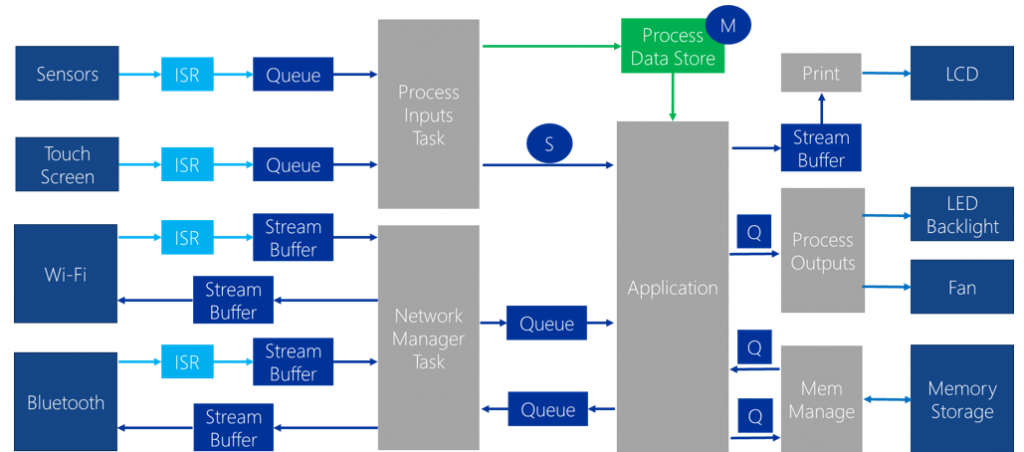
The diagram below shows a generic but well-structured architecture incorporating these elements.
3. Designing an Architecture: A Case Study
Let's apply these concepts to a practical problem that builds on your previous work.
Problem Statement:
We want to build a "smart fan" system. The system will:
- Control the speed of a DC motor (our fan) using the closed-loop controller you built.
- Periodically read the ambient temperature from an I2C temperature sensor.
- Adjust the motor's target speed based on the temperature: the hotter it is, the faster the fan runs.
- Allow a user to manually override the target speed by sending commands through the serial console (e.g.,
set_speed 400).
Let's design the architecture step-by-step.
Step 1: Identify the Tasks
Based on the requirements, we can identify three distinct, concurrent responsibilities:
motor_control_task: Responsible for running the periodic speed control loop (measure speed from PCNT, calculate error, update MCPWM). It needs to receive target speed commands.temp_sensor_task: Responsible for periodically waking up, reading the temperature from the I2C sensor, and sending the reading to themotor_control_task.cli_task(Command Line Interface): Responsible for monitoring the serial port for user commands, parsing them, and sending new target speeds to themotor_control_task.
Step 2: Identify Data Flows & Communication
Now, let's figure out how these tasks communicate.
- From
cli_tasktomotor_control_task: The CLI task needs to send a target speed (an integer) to the motor task. A queue, let's call itg_speed_cmd_queue, is perfect for this. The CLI task writes the new speed to the queue, and the motor task checks the queue at the start of its control loop. - From
temp_sensor_tasktomotor_control_task: The sensor task needs to send temperature data (a float) to the motor task. Similarly, a queue (g_temp_data_queue) is a great choice. The motor task can use the latest temperature reading from this queue to determine its automatic setpoint.
Using queues decouples the tasks. The sensor task doesn't need to know anything about the motor task, other than where to send its data.
Step 3: Identify Shared Resources & Synchronization
What resources are used by more than one task?
- I2C Bus: The
temp_sensor_taskuses the I2C bus. What if we later add a display that also uses I2C? The I2C peripheral is a shared resource. All access to it should be protected by a mutex, let's call itg_i2c_mutex. - Serial Port (UART): The
cli_taskuses the UART to receive commands. What if other tasks also want to print log messages to the same UART for debugging? The UART is a shared resource. We should protect all write access to it with ag_uart_mutex. - Control Logic: The
motor_control_taskimplements the logictarget_speed = f(temperature). It also accepts manual overrides. This logic itself represents a state machine that is primarily managed within the motor task. If the state were complex and modified by multiple tasks, the state variables themselves would need protection.
Step 4: Diagram the Architecture
Now we can combine these elements into a diagram. We don't need formal UML; simple boxes and arrows are sufficient to convey the design.
System Architecture: Smart Fan
+---------------------------+       +-------------------------+       +------------------------+
|      temp_sensor_task     |       |   motor_control_task    |       |        cli_task        |
| (Priority: 2, Runs every 5s) |       | (Priority: 3, Runs every 100ms) |       | (Priority: 2, Blocks on UART) |
+-------------+-------------+       +------------+------------+       +------------+-----------+
              |                             ^      ^                      |
              |                             |      |                      |
              |     Uses I2C Bus            |      |   Parses commands    |
              v                             |      |                      v
      +---------------+             [g_temp_data_queue] [g_speed_cmd_queue]    +----------------+
      |   I2C Bus     |<-- (Lock) ---+                      +---- (Lock) -->|   UART Port    |
      |  (Sensor)     |                                                   | (Serial Console) |
      +---------------+                                                   +----------------+
            (M) g_i2c_mutex                                                    (M) g_uart_mutex

      +---------------+            +------------------+
      | PCNT Hardware |<-----------| MCPWM Hardware   |
      |  (Encoder)    |            | (H-Bridge)       |
      +---------------+----------->+------------------+
- Boxes: Represent tasks and hardware resources.
- Arrows with
[]: Represent FreeRTOS Queues for data transfer. (M)and(Lock): Indicate a Mutex protecting a shared resource.- Task details: Include a hint about priority and scheduling, which are key design decisions. Higher numbers mean higher priority. The motor control is time-sensitive, so it gets the highest priority.
This diagram clearly communicates the design to other developers (or your future self!) and helps identify potential issues before a single line of code is written.
The following case study video provides another excellent example of this design process in action.
#381 How to work with a Real Time Operating System and is it any good? (FreeRTOS, ESP32)
Let's watch how Andreas Spiess applies this exact thought process to design a 'Morse Trainer' project.
Watch the segment from 08:29 to 12:27. Pay close attention to how he first specifies the project's parallel requirements and then explicitly identifies the need for three tasks, two queues, and three shared resources that require protection. This is a perfect real-world demonstration of system architecture design.
Test your understanding!
You are designing an automated plant watering system. It needs to:
- Periodically check a soil moisture sensor (analog input via ADC).
- If moisture is below a threshold, run a water pump (a simple GPIO-controlled motor) for 10 seconds.
- Allow a user to connect via Bluetooth Low Energy (BLE) to check the last moisture reading and manually trigger the pump.
Based on these requirements, identify the main tasks, the necessary communication/synchronization objects (queues, mutexes, etc.), and briefly describe their roles.
Show answer
A good architecture would include:
-
Tasks:
MoistureSensorTask: Runs periodically (e.g., every hour). It reads the ADC for the moisture level. It updates a shared variable with this reading. If the reading is below a threshold, it sends a "start pump" command.PumpControlTask: Waits for commands. When it receives a command, it turns on the pump's GPIO, waits for 10 seconds (usingvTaskDelay), and then turns it off.BLETask: Manages the BLE connection and services. When a request for the moisture level comes in, it reads the shared variable. When a "manual water" command is received, it sends a command to thePumpControlTask.
-
Communication & Synchronization Objects:
pump_command_queue(Queue): This queue is used to send commands (e.g., an enumSTART_PUMP) to thePumpControlTask. Both theMoistureSensorTaskand theBLETaskcan write to this queue, decoupling them from the pump's implementation and safely handling requests from multiple sources.g_moisture_mutex(Mutex): A mutex is needed to protect a shared global variable,g_latest_moisture_reading. TheMoistureSensorTasklocks the mutex before writing the new ADC value, and theBLETasklocks it before reading the value. This ensures atomic access and prevents theBLETaskfrom reading a partially updated value.
Conclusion
In this lesson, you've learned the fundamental principles of designing a multi-tasking application architecture. This is a pivotal skill that elevates you from writing code that simply works to engineering systems that are robust, scalable, and maintainable.
Key Takeaways:
- Designing an embedded system starts with decomposing requirements into a set of concurrent tasks.
- Queues are the primary mechanism for passing data safely between tasks.
- Mutexes are essential for protecting shared resources (like hardware peripherals or global data) from concurrent access issues (race conditions).
- A system architecture diagram is a simple but powerful tool for visualizing your design, identifying interactions, and spotting potential problems before you start coding.
Now that you have the blueprint, the following lessons in this module will guide you through the implementation. In the next lesson, we will start by implementing the temp_sensor_task, focusing on how to read from a sensor in a dedicated FreeRTOS task and trigger it periodically.