Hello! Welcome back to our module on Multi-Peripheral System Integration.
In our last lesson, we designed the high-level architecture for a "smart fan" project. We identified the key tasks, queues, and mutexes needed to build a robust system. One of those key components was the temp_sensor_task, responsible for periodically reading the ambient temperature.
Today, we will bring that part of our design to life. This lesson focuses on the learning outcome: Implement environmental sensor reading in a dedicated FreeRTOS task using a timer for periodic sampling.
We'll break this down into three parts:
- How to communicate with a typical environmental sensor using the I2C protocol and the ESP-IDF driver.
- Why using a dedicated timer is superior to simple delays for periodic events.
- How to combine these concepts into a clean, efficient, and reusable FreeRTOS pattern: using a software timer to trigger a dedicated sensor-reading task.
This lesson directly implements the sensor-reading block from the architecture diagram we created, moving us one step closer to our fully integrated system.
1. Reading from an I2C Environmental Sensor
Most environmental sensors, like temperature, humidity, or pressure sensors, use a communication protocol called I2C (Inter-Integrated Circuit). It's a simple and effective two-wire bus (SDA for data, SCL for clock) that allows a microcontroller to talk to multiple peripheral devices.
To see how this works in practice with the ESP-IDF, we'll watch a tutorial that demonstrates reading from a TMP102 temperature sensor. The concepts apply to many other I2C sensors like the popular BME280.
ESP32 - I2C with ESP-IDF Tutorial
The video 'ESP32 - I2C with ESP-IDF Tutorial' by Shawn Hymel provides a thorough walkthrough of the entire process, from understanding the sensor's datasheet to writing the code.
Please watch two key segments: I2C API Overview (04:13 - 05:40): Focus on the general pattern: initialize the bus, add a device to it, and then use the device handle to transmit/receive data. Pay attention to the i2c_master_transmit_receive function, which is key for reading from sensor registers. Reading and Converting Data (13:10 - 15:31): Observe how the main loop is structured. It calls i2c_master_transmit_receive to get raw data from the sensor and then performs some bit-wise math to convert that raw data into a human-readable temperature in degrees Celsius. This two-step process (read raw -> convert) is very common.
As you saw, the core steps using the ESP-IDF driver are:
- Configure the I2C Bus: Define which GPIO pins you're using for SDA and SCL and initialize the bus controller. You only do this once.
- Add a Device: Configure the specific I2C device by providing its bus address (from the datasheet) and clock speed. You get a
handleto this device. - Communicate: Use the device handle with functions like
i2c_master_transmit_receiveto read from or write to the sensor's internal registers.
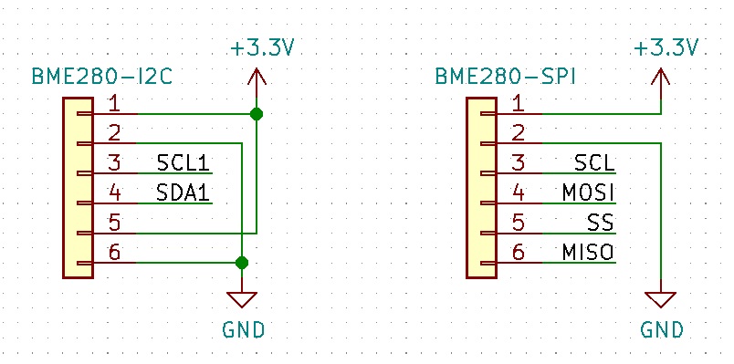
The physical connection is straightforward. The image below shows the I2C wiring for a BME280 sensor, which is very similar for any I2C device.
2. The Right Way to Do "Periodic": Software Timers
Now that we know how to read from the sensor, we need to decide when. Our requirement is to do it periodically (e.g., every 5 seconds). A simple approach might be to create a task with a loop like this:
while(1) {
    read_sensor_value();
    vTaskDelay(pdMS_TO_TICKS(5000)); // Wait for 5 seconds
}
This works, but it has drawbacks:
- Drift: The actual period will be 5 seconds plus the time it takes to execute
read_sensor_value(). This error accumulates, causing timing drift. - Inflexibility: The timing logic is tightly coupled with the action. This makes the code harder to manage if other events need to influence the timing.
A much cleaner and more accurate solution is to use a FreeRTOS Software Timer. These are lightweight timers managed by the RTOS itself. You can create a timer, tell it to expire at a certain interval, and provide a callback function that gets executed upon expiry.
This video provides an excellent explanation of what software timers are and why they are useful.
Introduction to RTOS Part 8 - Software Timer | Digi-Key Electronics
The Digi-Key video 'Introduction to RTOS Part 8 - Software Timer' clearly explains the concept and architecture of FreeRTOS software timers.
Please watch from the beginning to 04:03. Focus on: The comparison between using vTaskDelay, hardware timers, and software timers. How the 'timer service task' (or daemon) manages all software timers and executes their callbacks, separating the timing from your application tasks.
The key takeaway is that a software timer lets us schedule an action without dedicating a task to just waiting. It's the perfect tool for our periodic sampling requirement.
3. Implementation: The Timer-Notification Pattern
We will now implement the most common and efficient pattern for this scenario: a software timer that doesn't do the work itself, but simply notifies the dedicated sensor task that it's time to run.
This approach, detailed in the article below, keeps the timer callback function extremely short and fast, which is a critical best practice in RTOS development.
ESP32 FreeRTOS Multitasking Project Tutorial
The article 'ESP32 FreeRTOS Multitasking Project Tutorial' from ControllersTech provides a fantastic walkthrough of the exact architecture we are building.
Please read the sections 'Task 1: ADC Sensor Reading via FreeRTOS Timer' and 'Using Timers & Notifications for Periodic Scheduling'. Pay close attention to the diagram and the description of how the timer triggers the ADC task via a notification. This is the core logic we will implement.
Let's build this step-by-step in C++.
Step 1: Define the Task, Timer, and Handles
First, we set up the necessary global variables. We need handles for our task and timer so we can refer to them.
#include "freertos/FreeRTOS.h"
#include "freertos/task.h"
#include "freertos/timers.h"
// Include I2C driver
#include "driver/i2c.h"

// Task and Timer handles
static TaskHandle_t s_sensor_task_handle = NULL;
static TimerHandle_t s_sensor_timer_handle = NULL;

// Forward declaration of our task function
void sensor_task(void *pvParameters);
Step 2: The Timer Callback Function
This function will be executed by the FreeRTOS timer service every time our timer expires. Its only job is to give a notification to our sensor task.
// This callback is executed in the context of the timer service task.
static void sensor_timer_callback(TimerHandle_t xTimer) {
    // Check if the task handle is valid before sending a notification.
    if (s_sensor_task_handle != NULL) {
        // Send a notification to the sensor_task.
        // The xHigherPriorityTaskWoken parameter is not used here but is required for ISR versions.
        BaseType_t xHigherPriorityTaskWoken = pdFALSE;
        vTaskNotifyGiveFromISR(s_sensor_task_handle, &xHigherPriorityTaskWoken);
        // This is a good practice even if we don't expect a context switch here.
        portYIELD_FROM_ISR(xHigherPriorityTaskWoken);
    }
}
Note: vTaskNotifyGiveFromISR is safe to call from a timer callback, which runs in a different context than your task. It's a lightweight way to signal a task.
Step 3: The Dedicated Sensor Task
This task is the "worker." It spends most of its time blocked, waiting for a notification. When it receives one, it wakes up, does its work (reads the sensor), and then goes back to waiting.
void sensor_task(void *pvParameters) {
    // In a real application, the I2C handle would be initialized once and passed in.
    // For simplicity, we'll assume it's configured.
    // i2c_master_dev_handle_t i2c_dev_handle = (i2c_master_dev_handle_t)pvParameters;

    while (1) {
        // Block indefinitely until a notification is received from the timer callback.
        ulTaskNotifyTake(pdTRUE, portMAX_DELAY);

        printf("Timer triggered! Reading sensor...\n");

        // --- I2C Reading Logic Goes Here ---
        // 1. Define buffer for raw data.
        uint8_t raw_data[2];
        // 2. Define sensor register to read from.
        uint8_t temp_register = 0x00; // Example: Temperature register for TMP102

        // This is a simplified call based on the video. Error handling is crucial in production.
        // esp_err_t ret = i2c_master_transmit_receive(i2c_dev_handle, &temp_register, 1, raw_data, 2, -1);

        // if (ret == ESP_OK) {
        //     // 3. Convert raw data to a meaningful value.
        //     int16_t raw_temp = (raw_data[0] << 8) | raw_data[1];
        //     float temperature = (raw_temp >> 4) * 0.0625; // Conversion for TMP102
        //     printf("Temperature: %.2f C\n", temperature);
        //
        //     // 4. Send the data to a queue (to be used by another task).
        //     // xQueueSend(g_temp_data_queue, &temperature, 0);
        // } else {
        //     printf("Failed to read from sensor\n");
        // }
    }
}
Step 4: Initialization in app_main
Finally, in our main application entry point, we create the task and the timer, and then start the timer.
void app_main(void) {
    // In a full app, you would initialize I2C here.

    // Create the sensor task.
    xTaskCreate(sensor_task,          // Task function
                "sensor_task",        // Name for debugging
                2048,                 // Stack size
                NULL,                 // Parameters (e.g., I2C handle)
                5,                    // Priority
                &s_sensor_task_handle); // Task handle

    // Create a periodic software timer.
    s_sensor_timer_handle = xTimerCreate("sensor_timer",        // Name for debugging
                                         pdMS_TO_TICKS(5000),   // Period in ticks (5000 ms)
                                         pdTRUE,                // Auto-reload -> periodic
                                         (void *)0,             // Timer ID, not used
                                         sensor_timer_callback); // Callback function

    // Start the timer. It will begin expiring after the first period.
    if (s_sensor_timer_handle != NULL) {
        xTimerStart(s_sensor_timer_handle, 0);
    }
}
This complete structure cleanly separates the periodic trigger (the timer) from the action (the task), creating a robust and efficient solution.
Test your understanding!
Imagine you need to change the sensor sampling rate from every 5 seconds to every 200 milliseconds.
- Which function call would you modify?
- What would the new parameters look like?
Show answer
- You would modify the
xTimerCreatefunction call insideapp_main. - You would change the second parameter, which is the timer period. The new call would look like this:
This single change adjusts the entire periodic behavior without touching the sensor reading logic itself, highlighting the power of this decoupled design.s_sensor_timer_handle = xTimerCreate("sensor_timer", pdMS_TO_TICKS(200), // Changed from 5000 to 200 pdTRUE, (void *)0, sensor_timer_callback);
Conclusion
In this lesson, you've implemented a fundamental building block of any complex embedded system: a periodic, non-blocking sensor reading task. This is a significant step beyond simple linear programming and is central to creating responsive, multi-peripheral applications.
Key Takeaways:
- I2C Communication: The ESP-IDF provides a driver API to initialize the I2C bus, add devices, and perform read/write operations.
- Periodic Actions: For periodic tasks, FreeRTOS software timers are more accurate and efficient than using
vTaskDelayin a loop. - Timer-Notification Pattern: The most robust way to implement a periodic task is to have a software timer's callback send a task notification to a dedicated worker task. This keeps the callback short and decouples the timing logic from the task's execution logic.
We have now successfully implemented the temp_sensor_task from our system architecture. In the next lesson, we will focus on another block from our diagram: "Implement motor control logic in a separate FreeRTOS task that responds to commands." We will build the task that manages the motor and receives setpoints from a queue, preparing it for integration with the sensor task we built today.