Hello and welcome to the final lesson in our module on Advanced Motor Control.
In the past few lessons, you've mastered the essential components of motor control. You learned to generate complementary PWM signals with dead-time using the MCPWM peripheral to drive an H-bridge, and you configured the PCNT peripheral to read quadrature encoder signals for position and direction feedback. Now, it's time to connect these two pieces to close the loop.
This lesson directly addresses the learning outcome: Implement a simple closed-loop speed control algorithm (e.g., Proportional control) using MCPWM and PCNT feedback. We will build a system that measures a motor's actual speed and automatically adjusts its power to match a desired target speed. Given your mechanical engineering background, the principles of feedback control will be familiar; today, we focus on their practical implementation on an embedded system.
1. The Architecture of a Closed-Loop System
A closed-loop control system continuously measures a system's output (the Process Variable or PV) and compares it to a desired value (the Setpoint). The difference, or error, is fed into a controller, which calculates a corrective action to be applied by an actuator.
For our DC motor system, the components are:
- Setpoint: The target speed in RPM we want the motor to achieve.
- Sensor (PCNT): Measures the encoder pulses to determine the motor's current rotation.
- Controller (ESP32): Our C++ code that calculates the current speed, finds the error, and computes a new motor power level.
- Actuator (MCPWM + H-Bridge): Applies the calculated power level to the motor by adjusting the PWM duty cycle.
- Plant: The DC motor itself.
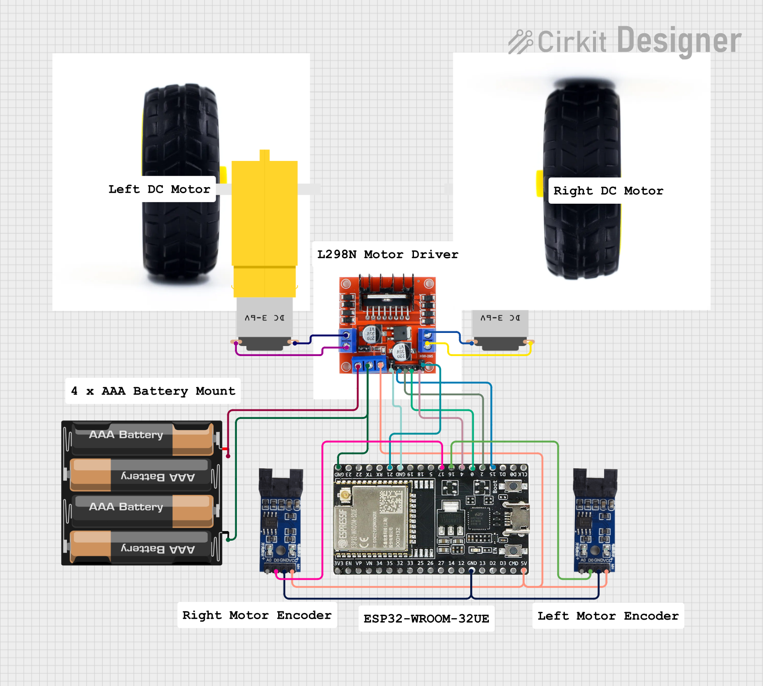
Our control loop will execute periodically:
- Measure: Get the latest pulse count from the PCNT peripheral.
- Calculate: Determine the actual motor speed (RPM) based on the change in pulse count over a fixed time interval.
- Compare: Compute the error:
error = target_speed - actual_speed. - Act: Calculate a new PWM duty cycle based on the error and update the MCPWM comparator.
2. From Pulses to Speed
The first step inside our control loop is to convert the raw pulse count from the PCNT into a meaningful speed measurement, like revolutions per minute (RPM).
To do this, we need to sample the pulse count at a regular interval. Let's say we read the counter every 100 milliseconds.
count_at_t0: The pulse count frompcnt_unit_get_count()at the beginning of the interval.count_at_t1: The pulse count at the end of the interval (100 ms later).delta_counts = count_at_t1 - count_at_t0.delta_time_s: The sampling interval in seconds (0.1 s).
We also need to know the resolution of our encoder system, i.e., how many counts correspond to one full revolution. This depends on your encoder's native Pulses Per Revolution (PPR) and the decoding mode you used in the PCNT configuration. From the last lesson, if you are using 2x decoding with an encoder that has N pulses per revolution, then:
pulses_per_rev = 2 * N
The speed calculation is then:
For example, if your 20-PPR encoder (using 2x decoding, so pulses_per_rev = 40) produces 30 counts in a 100 ms interval, the speed is:
This calculation will be the core of our feedback measurement.
3. Implementing a Proportional (P) Controller
The simplest form of a feedback controller is a Proportional (P) controller. Its logic is straightforward: the corrective action is directly proportional to the size of the error.
Where:
error = setpoint_speed - measured_speed.- is the proportional gain, a tuning constant that determines how aggressively the controller reacts to error.
The Control Output must then be translated into a valid duty cycle for the MCPWM peripheral. A critical step is to combine this proportional correction with a baseline duty cycle and then constrain the result to the valid range (e.g., 0% to 100%).
A simple implementation might look like this:
// --- Inside your periodic control task ---

// 1. Calculate speed (as shown in the previous section)
float measured_speed = calculate_speed_from_encoder();

// 2. Calculate error
float error = target_speed - measured_speed;

// 3. Calculate proportional correction
float correction = Kp * error;

// 4. Calculate new duty cycle
// Start with the current duty and add the correction
float new_duty_cycle = current_duty_cycle + correction;

// 5. Clamp the duty cycle to a valid range (e.g., 0 to 100)
if (new_duty_cycle > 100.0f) {
    new_duty_cycle = 100.0f;
} else if (new_duty_cycle < 0.0f) {
    new_duty_cycle = 0.0f;
}

// 6. Update the hardware
// 'timer_period' is the value for 100% duty cycle
uint32_t mcpwm_compare_value = (uint32_t)(new_duty_cycle / 100.0f * timer_period);
ESP_ERROR_CHECK(mcpwm_comparator_set_compare_value(comparator, mcpwm_compare_value));

// Store the new duty cycle for the next iteration
current_duty_cycle = new_duty_cycle;
Tuning :
- Low : The controller reacts slowly. It may not be able to reach the setpoint, resulting in a large steady-state error.
- High : The controller reacts aggressively. This can lead to overshoot (the speed exceeds the setpoint) and oscillations around the setpoint. If too high, the system becomes unstable.
Tuning is an iterative process of adjusting to find a balance between responsiveness and stability.
Test your understanding!
You've implemented your P-controller. You notice that for a target of 300 RPM, the motor stabilizes at 280 RPM. You increase , and it stabilizes at 290 RPM. You increase further, and it stabilizes at 295 RPM but starts to oscillate slightly.
Why does this persistent steady-state error exist, and what does this tell you about the limitations of a pure P-controller?
Show answer
A pure P-controller requires a non-zero error to produce a non-zero output. For a motor with a constant load (like friction), a certain amount of power (duty cycle) is required just to maintain a steady speed.
The control law is Output = Kp * error. To generate the required steady-state power, there must be a remaining error. If the error were zero, the output would be zero, and the motor would stop.
Increasing reduces this error because a smaller error is needed to generate the same required output (Output = Kp * error). However, as you observed, making too large leads to instability. This demonstrates the primary limitation of P-control: the trade-off between reducing steady-state error and maintaining stability. This is why more advanced controllers add an Integral (I) term, which accumulates past errors to eliminate steady-state error over time.
4. A Practical Code Example
The ESP-IDF provides an excellent example that implements a full PID (Proportional-Integral-Derivative) controller for speed control. While it includes the 'I' and 'D' terms, its structure is perfect for understanding how to implement the 'P' control we've just discussed.
Let's study this example to see how the theory translates into a real application.
Motor Control Pulse Width Modulator (MCPWM)
The official ESP-IDF documentation for the MCPWM peripheral includes a complete example for brushed DC motor speed control. This example integrates MCPWM for output, PCNT for feedback, and a PID control algorithm running in a FreeRTOS task. Please read the description and prepare to analyze its source code.
In the 'Application Examples' section, locate the example named 'peripherals/mcpwm/mcpwm_bdc_speed_control'. Click the link to open the source code on GitHub. We will focus on how it calculates speed and applies the control output.
After you have the code open, let's dissect the most important parts:
-
The Control Task: In
mcpwm_bdc_speed_control_main.c, you'll find a FreeRTOS taskpid_motor_control_task. This is the periodic loop we've been discussing. It usesvTaskDelayto run at a fixed interval (PID_CONTROL_LOOP_PERIOD_MS). -
Calculating Speed: Inside the task, a call is made to
pcnt_unit_get_count(). The code then calculatesmotor_pulse_count, which is ourdelta_counts. The speed in RPM is calculated with a similar formula to ours:g_motor_speed_rpm = (float)(motor_pulse_count * (1000 / PID_CONTROL_LOOP_PERIOD_MS) * 60 / BDC_ENCODER_PULSE_PER_REV); -
The PID (and P) Calculation: The code then calls a function
pid_compute. This function calculates the error and then computes the P, I, and D terms. For our purposes, the key line is:p_term = s_pid_param.kp * error;This is exactly the proportional control logic we designed. The function then sums the terms to get a final
output. -
Applying the Output: The
outputfrompid_computeis used to update the motor's duty cycle. The example cleverly uses the sign of the output to set the direction (via a GPIO) and the magnitude to set the speed. The speed is set by updating the MCPWM comparator:ESP_ERROR_CHECK(mcpwm_comparator_set_compare_value(mcpwm_cmpr, output));
This example demonstrates a robust, real-world implementation of the concepts we've covered. It brings together FreeRTOS tasks, the PCNT peripheral, and the MCPWM peripheral into a single, functional control system.
Conclusion
Congratulations on completing the Advanced Motor Control module! You have successfully closed the loop, progressing from simple open-loop control to a sophisticated feedback system.
Key Takeaways:
- A closed-loop system uses feedback from a sensor (PCNT) to allow a controller (ESP32) to adjust an actuator (MCPWM) to match a setpoint.
- Speed can be calculated by measuring the change in encoder pulses over a known time interval.
- A Proportional (P) controller provides a corrective output proportional to the error (
output = Kp * error), offering a simple but effective control strategy. - The controller's output must be mapped and clamped to the valid range of the MCPWM duty cycle.
- Tuning the proportional gain is a critical step to balance system responsiveness against stability.
In the next module, Multi-Peripheral System Integration, we will expand on these ideas. You've now built a complex subsystem. Next, you'll learn how to integrate this motor controller with other peripherals, like environmental sensors, and manage them all concurrently using FreeRTOS. We'll explore how to design robust multi-task applications where different components communicate and share resources safely.