Hello and welcome back to our module on Advanced Motor Control.
In our last lesson, we mastered the "output" side of motor control by configuring the MCPWM peripheral to generate complementary PWM signals with precise dead-time insertion. This allows us to safely drive an H-bridge. Now, we need to close the loop. To control a motor effectively, we must be able to measure its response—specifically, its position, direction, and speed.
This lesson focuses on the "input" side of the control system, addressing the learning outcome: Configure the PCNT (Pulse Counter) peripheral to read quadrature encoder pulses for motor speed and direction feedback. We will explore how encoders work and then dive into the specifics of using the ESP32's dedicated hardware to interpret their signals efficiently.
1. Understanding Quadrature Encoders
A rotary encoder is a sensor that translates the angular position of a shaft into a digital signal. For motor control, we most commonly use incremental quadrature encoders. These encoders don't report an absolute position but rather generate pulses as the shaft rotates, from which we can deduce movement and direction.
They typically have two output channels, usually called Phase A and Phase B. The signals on these channels are square waves that are 90 degrees out of phase with each other. This phase difference is the key to determining the direction of rotation.
To get a solid grasp of this core concept, please watch the following video.
Understanding and using quadrature encoders - The Byte Sized Engineer | DigiKey
This video from Digi-Key provides an excellent conceptual foundation for how quadrature encoders work. It visually demonstrates how the two out-of-phase signals are used to determine both the amount of rotation and, crucially, its direction.
Please watch from the beginning until 07:36. Pay close attention to how the phase relationship between the 'A' and 'B' signals changes when the direction of rotation is reversed. The video also introduces the practical issue of switch 'bouncing', which we'll address with a hardware feature later.
As the video explained, the direction of rotation is determined by which signal's rising edge leads the other.
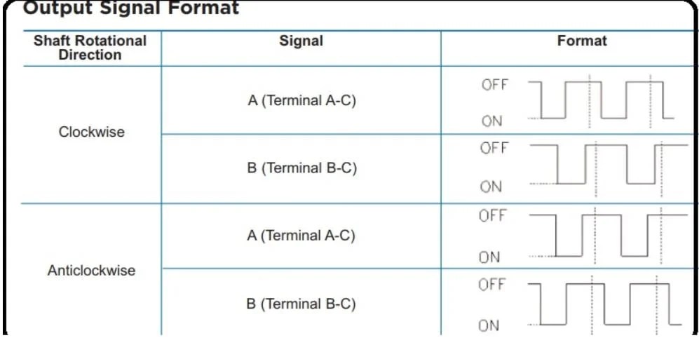
The video demonstrated a method using GPIO interrupts on an Arduino. While this works, it can consume significant CPU time, especially at high rotation speeds. The ESP32 provides a much more elegant and efficient solution: the Pulse Counter (PCNT) peripheral, a hardware module designed specifically for tasks like this.
2. The ESP32 Pulse Counter (PCNT) Peripheral
The PCNT peripheral can autonomously count incoming pulses on a GPIO pin. More importantly, it can use the logic level of a second GPIO pin to control how it counts (e.g., incrementing, decrementing, or holding). This makes it perfectly suited for decoding quadrature encoder signals directly in hardware, freeing up the CPU for other tasks like running your control algorithm.
Let's explore the theory and different ways to decode the encoder signals to achieve higher resolution.
Chapter 166: Encoder Interface with PCNT
The article 'Encoder Interface with PCNT' from CircuitLabs.net provides an excellent technical overview. We'll start with the sections that explain the theory behind quadrature encoders and the different decoding modes.
Please read the sections 'Introduction', 'Theory', and 'Quadrature Decoding Modes'. These sections will introduce you to the PCNT module, refresh the A/B/Z signal concepts, and explain the difference between 1x, 2x, and 4x decoding resolutions.
Decoding Modes and Resolution
As you just read, we can increase the effective resolution of an encoder by choosing to count more than just the rising edge of one channel.
- 1x Decoding: Counts one edge (e.g., rising) on one channel (e.g., Phase A). You get N counts per revolution, where N is the encoder's native Pulses Per Revolution (PPR).
- 2x Decoding: Counts both the rising and falling edges on one channel. This doubles the resolution to 2N counts per revolution.
- 4x Decoding: Counts every edge on both channels (A rising, B rising, A falling, B falling). This provides the highest resolution of 4N counts per revolution.
Using a single PCNT unit, the most common and efficient method is 2x decoding, which offers a great balance of resolution and implementation simplicity. We will focus on this method.
3. Configuring PCNT for 2x Quadrature Decoding
To implement 2x decoding, we'll connect Phase A of the encoder to the PCNT's edge input and Phase B to its level control input. We then configure the peripheral's behavior with two key function calls:
pcnt_channel_set_edge_action(): This tells the PCNT what to do by default on a rising or falling edge of the Phase A signal.pcnt_channel_set_level_action(): This defines how the default action is modified based on the logic level of the Phase B signal.
Let's see exactly how to set this up.
Chapter 166: Encoder Interface with PCNT
This next section of the same article provides the exact configuration logic for 1x and 2x decoding modes. It includes a table that clearly lays out the required settings.
Please read the sections titled 'Configuring PCNT for Quadrature Encoders' and 'Debouncing and Filtering'. Focus on understanding the logic described for the 2x Decoding setup.
Let's break down the logic for 2x decoding. The configuration is:
-
pcnt_channel_set_edge_action(channel, PCNT_CHANNEL_EDGE_ACTION_INCREASE, PCNT_CHANNEL_EDGE_ACTION_DECREASE);- Default action on Phase A rising edge:
INCREASE - Default action on Phase A falling edge:
DECREASE
- Default action on Phase A rising edge:
-
pcnt_channel_set_level_action(channel, PCNT_CHANNEL_LEVEL_ACTION_INVERSE, PCNT_CHANNEL_LEVEL_ACTION_KEEP);- If Phase B is HIGH:
INVERSEthe default action. - If Phase B is LOW:
KEEPthe default action.
- If Phase B is HIGH:
Combining these rules gives us the complete behavior:
- A rises, B is low:
INCREASE(kept) -> Count +1 - A falls, B is high:
DECREASE(kept) -> Count -1 (Incorrect for CW, see below)
Let's trace a full clockwise rotation (where A leads B):
- A rises, B is low: Action is
INCREASE, B is low so weKEEP-> Count +1 - B rises, A is high: (No edge on A, no action)
- A falls, B is high: Action is
DECREASE, B is high so weINVERSE-> Count +1 - B falls, A is low: (No edge on A, no action)
The article's logic table has a small error in its DECREASE/INCREASE labels but the resulting behavior is correct. Let's trace it correctly:
- A pos edge, B low: Action is
INCREASE. B is low, so weKEEPit. Result: Increment. (Correct for CW) - A pos edge, B high: Action is
INCREASE. B is high, so weINVERSEit. Result: Decrement. (Correct for CCW) - A neg edge, B low: Action is
DECREASE. B is low, so weKEEPit. Result: Decrement. (Correct for CCW) - A neg edge, B high: Action is
DECREASE. B is high, so weINVERSEit. Result: Increment. (Correct for CW)
This combination correctly increments the counter twice per cycle for clockwise rotation and decrements it twice for counter-clockwise rotation, achieving 2x decoding.
Finally, the article mentions the glitch filter. This is the hardware solution to the switch "bouncing" problem mentioned in the video. By telling the PCNT to ignore very short pulses (e.g., < 1000 ns), we can get a clean count without any software overhead.
Test your understanding!
You've wired your encoder and implemented the 2x decoding logic above, but you find that turning the motor shaft clockwise causes the PCNT count to decrease instead of increase. Without changing any wiring, what are two distinct ways you could fix this in your software configuration?
Show answer
Here are two effective solutions:
-
Swap the GPIO roles: In the
pcnt_channel_config_tstruct, assign the GPIO connected to Phase B toedge_gpio_numand the GPIO connected to Phase A tolevel_gpio_num. This effectively swaps their roles in the decoding logic. -
Invert the level control logic: In the
pcnt_channel_set_level_action()call, swap the parameters to be(channel, PCNT_CHANNEL_LEVEL_ACTION_KEEP, PCNT_CHANNEL_LEVEL_ACTION_INVERSE). This flips the condition for when the edge action is inverted, thereby reversing the perceived direction. An equivalent method is to set theinvert_level_inputflag totruein thepcnt_channel_config_tstruct.
4. Practical Implementation
Now let's translate this theory into a working example. First, here is a typical wiring setup.
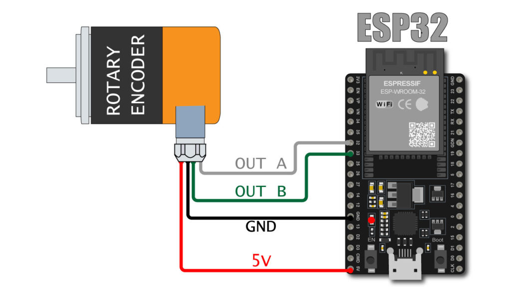
Now, let's examine the code that brings this to life.
Chapter 166: Encoder Interface with PCNT
The article provides a complete, self-contained example for initializing the PCNT for 2x decoding and printing the count to the serial monitor. Please study this code to see how the configuration steps we've discussed are put together.
Read and analyze the code in 'Example 1: Quadrature Encoder (2x Decoding) and Position Display'. Follow the numbered steps in the initialize_encoder function and see how they map to our discussion.
The code in the article follows a clear, structured approach using the modern ESP-IDF API:
- Create a PCNT Unit:
pcnt_new_unit()is called with a configuration that sets the counter's operational range (high_limit,low_limit). - Create a PCNT Channel:
pcnt_new_channel()associates the unit with the specific GPIOs for the edge (Phase A) and level (Phase B) inputs. - Set Actions: The crucial
pcnt_channel_set_edge_action()andpcnt_channel_set_level_action()calls are made to implement the 2x quadrature logic we dissected. - Add Glitch Filter:
pcnt_unit_set_glitch_filter()is configured to reject noise. A value around 1000 ns is a good starting point for common mechanical encoders. - Enable, Clear, and Start: Finally, the unit is enabled, its count is reset to zero, and it is started.
The app_main function then enters a simple loop that periodically calls pcnt_unit_get_count() to retrieve the hardware-maintained count and print it. This value is the raw position feedback from our motor.
Conclusion
In this lesson, you have learned how to transform the physical rotation of a motor shaft into a digital count that your ESP32 can use. This feedback is the missing piece of our motor control system.
Key Takeaways:
- Quadrature encoders use two 90-degree out-of-phase signals (A and B) to provide both position and direction information.
- The ESP32's PCNT peripheral is the ideal tool for this job, decoding encoder signals in hardware efficiently.
- The key to configuration is setting the
edge_action(what to do on an edge) andlevel_action(how to modify that action based on the other signal). - Using the glitch filter is essential for getting reliable counts from noisy mechanical encoders.
- The final result is a counter, accessible via
pcnt_unit_get_count(), that automatically tracks the motor's relative position.
In our next and final lesson of this module, we will put everything together. We will use the position count from the PCNT peripheral to calculate the motor's speed and create a simple closed-loop controller that adjusts the MCPWM duty cycle to maintain a target RPM.