Hello! Welcome back to your course on C++ for the ESP32.
In our last lesson, we explored how to read analog signals from the physical world using the Analog-to-Digital Converter (ADC). Today, we'll complete our tour of the ESP32's basic analog I/O capabilities by learning how to generate true analog signals using the Digital-to-Analog Converter (DAC).
This lesson addresses the learning outcome: Output analog voltages using the ESP32 DAC peripheral. You will learn how to take a digital number from your code and convert it into a specific, stable voltage level at one of the ESP32's output pins.
It's important to distinguish this from the PWM technique we used for the LEDC peripheral. PWM simulates an average analog voltage by rapidly switching a digital pin, which is great for controlling the power delivered to devices like LEDs or motors. The DAC, however, produces a true, continuous analog voltage, making it suitable for applications like generating audio waveforms or providing a precise reference voltage for other analog components.
1. DAC Fundamentals
The ESP32 is equipped with two independent DAC channels. Let's start with a video that provides a clear overview of their core features.
ESP32 Audio: I2S & Built-In DACs Explained
This video from atomic14 introduces the key characteristics of the ESP32's built-in DACs. It's a great starting point for understanding their capabilities and limitations.
Watch the following segments: 0:17 - 1:23: This covers the number of channels, resolution, voltage range, and the fixed GPIO pins for the DACs. It also briefly shows the relevant functions in both Arduino and ESP-IDF. 1:46 - 2:43: This part demonstrates the DAC's output with a multimeter and discusses its non-linearity, which is an important practical consideration.
Here are the essential takeaways from the video and the official documentation:
- Two Channels: The ESP32 has two DAC channels.
- DAC Channel 1 is hardwired to GPIO25.
- DAC Channel 2 is hardwired to GPIO26.
- 8-bit Resolution: The DAC converts a digital value in the range of 0 to 255 into an analog voltage.
- Voltage Output: The output voltage is proportional to the digital value, according to the formula:
Where is the reference voltage, typically the ESP32's 3.3V supply. This means a digital value of 0 gives ~0V, 127 gives ~1.65V, and 255 gives ~3.3V. - Limitations: As the video demonstrated, the ESP32's DAC is not perfectly linear. The output may not reach the true 0V and 3.3V rails, and the steps may not be perfectly even across the range. For highly precise applications, calibration would be necessary.

2. The ESP-IDF One-Shot DAC Driver
The ESP-IDF provides a few different drivers for the DAC. We will focus on the modern one-shot driver, which is designed for setting and holding a specific DC voltage. This is the most direct way to achieve our learning outcome.
The official ESP-IDF documentation is the best source for understanding the API.
Digital To Analog Converter (DAC) - ESP-IDF Documentation
Let's look at the official ESP-IDF documentation for the DAC. We will focus on the sections describing the one-shot mode, which is used for direct voltage output.
First, read the section 'Direct Voltage Output (One-shot/Direct Mode)'. Then, skim the API reference under the heading 'Functions' in the 'API Reference' section. Focus on the purpose of these three functions: dac_oneshot_new_channel() dac_oneshot_output_voltage() dac_oneshot_del_channel()
As you've seen in the documentation, the workflow for the one-shot driver is clean and stateful, involving handles to manage resources:
- Include the Header: You must include the specific header for the one-shot driver.
#include "driver/dac_oneshot.h" - Configure and Allocate: Create a
dac_oneshot_config_tstructure, specifying which channel you want to use. Then, calldac_oneshot_new_channel()to allocate the channel and get back a handle (dac_oneshot_handle_t). - Output Voltage: Call
dac_oneshot_output_voltage()with the handle and the desired 8-bit value (0-255). The DAC will immediately begin outputting the corresponding voltage and will hold it until changed or disabled. - Deallocate: When you are done with the DAC channel, call
dac_oneshot_del_channel()with the handle to release the resources.
This handle-based approach is a safer and more robust way to manage peripherals compared to older, global-style APIs.
3. Creating a C++ Wrapper
Just as we did for the ADC, we can make using the DAC much more convenient and object-oriented by creating a C++ wrapper class. This class will manage the handle and provide a simple, clean interface for our application code.
The tutorial below uses a similar idea, but it's based on an older, now-deprecated ESP-IDF DAC driver. We'll adapt its excellent class structure to our modern dac_oneshot API.
Basic ESP32 DAC C++ library - EmbeddedTutorials
This tutorial from EmbeddedTutorials.com shows how to build a C++ class for the DAC. We will use the structure of their CppDac class as a model, but we will implement it using the newer dac_oneshot functions from the official documentation.
Study the sections 'Define the DAC class in the header' and 'Implement the ADC Class methods' (the title is a typo, it means DAC). Pay close attention to the class design: The use of a private member variable for the channel. The constructor that initializes the channel. The public methods like SetVoltageByValue(uint8_t level) and SetVoltage(float voltage). Notice that it uses functions like dac_output_voltage directly. Our implementation will replace these with the dac_oneshot_... equivalents.
Our DacChannel Class
Let's design our C++ class, DacChannel, using the principles from the tutorial but with the correct, modern API.
DacChannel.h (Header File)
The header file declares the class interface. We'll include the necessary driver header and define our class structure.
#pragma once

#include "driver/dac_oneshot.h"

class DacChannel {
public:
    // Constructor: Initializes and allocates the DAC channel.
    DacChannel(dac_channel_t channel);

    // Destructor: Deallocates the DAC channel to free resources.
    ~DacChannel();

    // Sets the output based on an 8-bit value (0-255).
    esp_err_t setRaw(uint8_t value);

    // Sets the output based on a desired float voltage (0.0 - 3.3V).
    esp_err_t setVoltage(float voltage);

private:
    dac_oneshot_handle_t _handle; // Handle for the allocated DAC channel.
    dac_channel_t _channel;       // The channel ID (DAC_CHANNEL_1 or DAC_CHANNEL_2).
};
DacChannel.cpp (Implementation File)
Here, we implement the logic for the methods declared in our header file.
The constructor handles resource allocation (dac_oneshot_new_channel), and the destructor handles cleanup (dac_oneshot_del_channel). This is a key C++ pattern called RAII (Resource Acquisition Is Initialization), which ensures resources are automatically released when the object goes out of scope.
#include "DacChannel.h"
#include "esp_check.h" // For ESP_ERROR_CHECK

DacChannel::DacChannel(dac_channel_t channel) : _channel(channel) {
    dac_oneshot_config_t config = {
        .chan_id = _channel,
    };
    // Allocate the channel
    ESP_ERROR_CHECK(dac_oneshot_new_channel(&config, &_handle));
}

DacChannel::~DacChannel() {
    // Deallocate the channel
    ESP_ERROR_CHECK(dac_oneshot_del_channel(_handle));
}

esp_err_t DacChannel::setRaw(uint8_t value) {
    // Output the voltage using the 8-bit value
    return dac_oneshot_output_voltage(_handle, value);
}
Test your understanding!
Now, try to implement the setVoltage(float voltage) method yourself. It should:
- Take a
floatvoltage as input (e.g., 2.5). - Convert this voltage into an 8-bit integer (0-255). Assume the reference is 3.3V.
- Clamp the resulting integer to be within the valid 0-255 range to prevent invalid inputs.
- Call the
setRaw()method with the calculated value. - Return the result from
setRaw().
Show answer
Here is the implementation of the setVoltage method:
esp_err_t DacChannel::setVoltage(float voltage) {
    // Clamp the input voltage to the valid range (0.0V to 3.3V)
    if (voltage < 0.0f) {
        voltage = 0.0f;
    }
    if (voltage > 3.3f) {
        voltage = 3.3f;
    }

    // Convert float voltage to an 8-bit integer value
    uint8_t raw_value = static_cast<uint8_t>((voltage / 3.3f) * 255.0f);

    // Call our existing method to set the output
    return setRaw(raw_value);
}
This helper function makes the DAC much more intuitive to use, as you can think in terms of volts rather than raw digital values.
4. Practical Application
Now that we have our DacChannel class, using it in our main application is straightforward. Let's write a simple program that generates a "sawtooth" wave by slowly ramping the voltage up on DAC channel 1, then resetting it.
main.cpp
#include "freertos/FreeRTOS.h"
#include "freertos/task.h"
#include "DacChannel.h" // Our new class
#include <iostream>

// Create a global instance for DAC Channel 1 (GPIO25)
DacChannel dac1(DAC_CHANNEL_1);

extern "C" void app_main(void) {
    uint8_t value = 0;
    std::cout << "Starting DAC sawtooth wave example." << std::endl;

    while (true) {
        // Set the DAC output using the raw 8-bit value
        dac1.setRaw(value);

        // Optional: calculate and print the approximate voltage
        float voltage = (value / 255.0f) * 3.3f;
        printf("Set DAC output to %d, approx %.2fV\n", value, voltage);

        // Increment the value, wrapping around from 255 back to 0
        value++;

        // Delay for 20 milliseconds
        vTaskDelay(pdMS_TO_TICKS(20));
    }
}
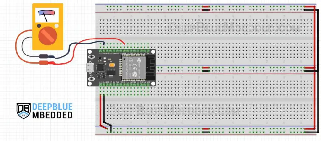
To test this, you can connect a multimeter between GPIO25 and GND. You should see the measured voltage slowly and smoothly climb from ~0V to ~3.3V over about 5 seconds (256 steps * 20ms/step) and then abruptly drop back to ~0V to repeat the cycle.
Conclusion
In this lesson, you have learned how to use the ESP32's Digital-to-Analog Converter to generate true analog voltages. This capability is fundamental for a wide range of applications, from creating audio signals to providing precise control voltages for external analog hardware.
Key Takeaways:
- The DAC converts a digital value (8-bit, 0-255) into a real analog voltage, which is different from PWM's simulated output.
- The ESP32 features two DACs on fixed pins: GPIO25 (Channel 1) and GPIO26 (Channel 2).
- The modern ESP-IDF API for this is the
dac_oneshotdriver, which uses handles for safe resource management. - Encapsulating the
dac_oneshotAPI within a C++ class (RAII) provides a clean, safe, and reusable interface for your projects. - You can create helper methods (like
setVoltage) to work with more intuitive units like volts instead of raw digital values.
In our next lesson, we will move on to a new topic: hardware timers. These are incredibly powerful peripherals that allow you to schedule events and generate signals with high precision, without blocking your main code with vTaskDelay. You'll see how timers can be combined with peripherals like the ADC and DAC to build even more sophisticated and responsive systems.