Hello! Welcome to the fourth module of your C++ for ESP32 course.
In our previous module, we finished our exploration of the ESP32's basic analog I/O by learning to use the Digital-to-Analog Converter (DAC). We saw how to generate true analog voltages and continued our practice of wrapping ESP-IDF drivers in C++ classes for safer and more intuitive use.
Today, we're moving into a new and powerful topic: hardware timers. While we've used vTaskDelay() to pause our code, this method isn't precise and blocks the task from doing other work. Hardware timers, in contrast, are like high-precision, independent stopwatches inside the microcontroller. They allow you to schedule events with nanosecond-level accuracy without halting your program's flow. This capability is fundamental for responsive and reliable embedded systems, especially in applications like motor control, data acquisition, and communication protocols.
This lesson addresses the learning outcome: Configure hardware timers on the ESP32 to trigger periodic events. We'll delve into the mechanics of how these timers work and learn how to use the ESP-IDF's General Purpose Timer (GPTimer) driver to set up a timer that triggers an event at a regular interval.
1. The Anatomy of a Hardware Timer
Before we write any code, it's essential to understand the building blocks of a hardware timer. Think of it as a digital clockwork mechanism. Your mechanical engineering background will make these concepts intuitive.
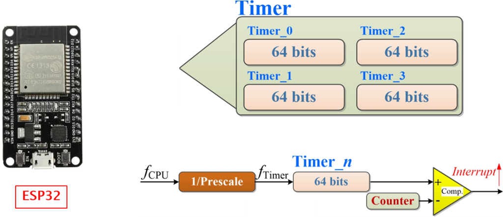
The key components in this flow are:
- Clock Source: This is the timer's fundamental heartbeat, usually derived from the ESP32's main Application Clock (APB_CLK), which typically runs at 80 MHz.
- Prescaler: An 80 MHz clock counts up incredibly fast. A prescaler is a frequency divider that slows this clock down to a more useful rate. For example, by dividing the 80 MHz clock by 80, we get a timer clock of 1 MHz, where each "tick" of the timer represents exactly 1 microsecond.
- Counter: This is a 64-bit register that increments by one on each tick of the prescaled clock. It's the part that does the actual counting.
- Alarm Value: This is a value we configure. When the counter's value matches our alarm value, the timer generates an alarm event (an interrupt).
- Auto-Reload: To create a periodic event, we can configure the timer to automatically reset its counter to a specific value (like 0) when the alarm triggers. This makes the process repeat indefinitely without any software intervention.
To get a feel for how these pieces work together in practice, let's watch a short video. It uses the Arduino framework, but the core concepts of prescalers and alarm values are identical.
ESP32 #56: ESP32 Timer & Multiple Timer & Changing Timer
This video from pcbreflux provides an excellent conceptual introduction to the ESP32 timers. Focus on how the prescaler and alarm value are used to create a precise 1-second interval.
Watch the first four minutes of the video (0:00 - 4:00). Pay attention to the explanation of the prescaler calculation (12.5 ns * 80 = 1000 ns = 1 µs) and how setting an alarm for 1,000,000 counts results in a 1-second period.
2. The Core Calculation: From Time to Ticks
To configure a timer, we need to determine the right combination of prescaler and alarm value to achieve our desired time interval. This is a straightforward design calculation.
The fundamental relationship is:
Let's work through an example. Suppose we want to create a periodic event every 50 milliseconds (0.05 s).
- Choose a Prescaler: We need to select a prescaler that gives us a reasonable timer resolution. The prescaler can be any value from 2 to 65536. A common choice is one that simplifies the math. Let's pick a prescaler of 800.
- Calculate Tick Frequency: The timer will now tick at a frequency of:
- Calculate Tick Period: The time for a single tick is the inverse of the frequency:
- Calculate Alarm Value: Now, how many 10 µs ticks do we need to count to reach 50 ms?
So, with a prescaler of 800 and an alarm value of 5000, our timer will trigger an event every 50 ms.
3. Configuring the Timer with ESP-IDF
The ESP-IDF provides a modern, robust driver called GPTimer. It uses a handle-based system, similar to the dac_oneshot driver we used in the last lesson. This approach ensures proper resource management.
The official ESP-IDF documentation is the best reference for this. We'll walk through its "Quick Start" guide for creating a periodic timer.
General Purpose Timer (GPTimer) - ESP32
The ESP-IDF documentation provides the definitive guide to using the GPTimer driver. We will focus on the sections that explain how to create a timer and configure it for periodic alarms.
Read the following two sections from the documentation: Creating and Starting a Timer: Focus on the gptimer_config_t structure. Note the resolution_hz field—this is a convenient way to set the timer's tick frequency directly, and the driver will calculate the prescaler for you. Triggering Periodic Alarm Events: Pay close attention to the gptimer_alarm_config_t structure, especially the alarm_count and auto_reload_on_alarm members. This is where you set the values from our calculation.
The API Workflow
The process of setting up a periodic timer follows a clear sequence of function calls. This flowchart from the documentation visualizes the lifecycle of a timer object.
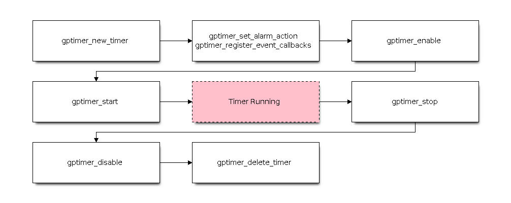
Let's break down the code needed to implement our 50 ms timer, following this workflow.
Step 1: Include the Header
#include "driver/gptimer.h"
Step 2: Create a Timer Instance
First, we define the basic timer configuration. Instead of setting the prescaler directly, the ESP-IDF gptimer driver lets us specify the desired resolution_hz (our tick frequency). The driver handles the prescaler calculation internally.
From our earlier calculation, we wanted a tick frequency of 100 kHz.
gptimer_handle_t gptimer = NULL;
gptimer_config_t timer_config = {
    .clk_src = GPTIMER_CLK_SRC_DEFAULT,
    .direction = GPTIMER_COUNT_UP,
    .resolution_hz = 100 * 1000, // 100 kHz resolution -> 1 tick = 10 µs
};
// Create the timer instance
ESP_ERROR_CHECK(gptimer_new_timer(&timer_config, &gptimer));
Step 3: Configure the Alarm Action
Next, we configure the alarm. We set the alarm count to 5000 and enable auto-reloading so the timer will run periodically.
gptimer_alarm_config_t alarm_config = {
    .alarm_count = 5000, // Period = 5000 ticks * 10 µs/tick = 50,000 µs = 50 ms
    .reload_count = 0,   // Reload the counter to 0 on alarm
    .flags.auto_reload_on_alarm = true,
};
// Set the alarm action
ESP_ERROR_CHECK(gptimer_set_alarm_action(gptimer, &alarm_config));
Test your understanding!
Let's say you want to change the timer to trigger an event every 2 seconds. Using the same resolution_hz of 100 kHz (where 1 tick = 10 µs), what value would you set for alarm_count?
Show answer
The desired period is 2 seconds, which is 2,000,000 microseconds.
Since each tick is 10 microseconds, the required alarm_count would be:
You would set .alarm_count = 200000; in the gptimer_alarm_config_t struct.
Step 4: Register an Event Callback
The timer needs to do something when the alarm triggers. We register a function (a "callback") that will be executed automatically. For now, our callback will be very simple. We'll explore these callback functions, known as Interrupt Service Routines (ISRs), in detail in the next lesson.
// A simple callback function (ISR)
static bool IRAM_ATTR example_timer_on_alarm_cb(gptimer_handle_t timer, const gptimer_alarm_event_data_t *edata, void *user_data)
{
    // For now, this function does nothing.
    // In the next lesson, we will use it to signal other parts of our program.
    return false;
}

// Register the callback
gptimer_event_callbacks_t cbs = {
    .on_alarm = example_timer_on_alarm_cb,
};
ESP_ERROR_CHECK(gptimer_register_event_callbacks(gptimer, &cbs, NULL));
Note the IRAM_ATTR attribute. This is a hint to the compiler to place this function in the ESP32's fast internal RAM, which is important for interrupt handlers. We'll cover this more next time.
Step 5: Enable and Start the Timer
Finally, with everything configured, we enable the timer driver and then start the counter.
// Enable the timer
ESP_ERROR_CHECK(gptimer_enable(gptimer));

// Start the timer
ESP_ERROR_CHECK(gptimer_start(gptimer));
At this point, the hardware timer is running completely independently of the CPU. Every 50 ms, it will automatically trigger the example_timer_on_alarm_cb function without any further intervention from our main code.
Conclusion
In this lesson, we've laid the groundwork for precise, non-blocking time management on the ESP32. You've learned how a hardware timer works from its fundamental components and, most importantly, how to configure it to trigger events at a specific periodic interval using the ESP-IDF.
Key Takeaways:
- Hardware timers allow you to schedule precise events without blocking your CPU with delays.
- Timers operate on a Clock Source, which is slowed down by a Prescaler to create a timer tick. A Counter increments on each tick until it reaches a configured Alarm Value.
- The ESP-IDF's GPTimer driver simplifies configuration by allowing you to set a
resolution_hz(tick frequency) directly. - The key to periodic events is calculating the correct
alarm_countfor a given resolution and enabling theauto_reload_on_alarmfeature. - The setup process involves creating a timer instance, setting the alarm action, registering a callback function for the alarm event, enabling the timer, and finally starting it.
We've set the stage perfectly for our next lesson: implementing timer interrupt service routines (ISRs). We've registered a placeholder callback function today; next time, we will dive into what an ISR is, the best practices for writing one, and how to use it to safely communicate with the rest of your application.