Hello! Welcome back to your course on C++ for the ESP32.
In our last lesson, we mastered analog-style output by using the LEDC peripheral to generate PWM signals. This is essential for controlling devices like motors and LEDs. Today, we'll explore the other side of the coin: analog input. We will learn how to read continuous voltage levels from analog sensors, a fundamental requirement for building systems that can perceive and react to the physical world.
This lesson directly addresses the learning outcome of reading analog values from sensors using the ESP32's Analog-to-Digital Converter (ADC) peripheral. By the end, you'll be able to take a varying voltage from a sensor, convert it into a digital number, and then translate that number into a meaningful physical unit like temperature or pressure.
1. The What and Why of Analog-to-Digital Conversion
Microcontrollers like the ESP32 are digital devices; they operate on discrete values of 1s and 0s (HIGH and LOW). However, the physical world is largely analog. Sensors that measure temperature, pressure, light, or distance typically produce a continuously varying voltage. An Analog-to-Digital Converter (ADC) is the bridge between this analog world and the digital world of the microcontroller.
The ADC's job is to measure an incoming analog voltage and convert it into a digital number. This process involves a few key characteristics.
ESP-IDF: ESP32 GPIO – Read Analog Input (ADC)
This article from Random Nerd Tutorials provides a great overview of the ESP32's ADC features. We'll start by reading the first part to understand the fundamentals.
Read the sections 'ESP32 ADC (Analog to Digital Converter) Modes', 'ESP32 ADC Range', 'ESP32 ADC is Non-linear', and 'ESP32 ADC GPIOs'. Focus on understanding the concepts of resolution, the non-linear response, and which pins can be used for ADC readings.
As you just read, here are the key takeaways for the ESP32's ADC:
- Resolution: The ESP32 ADC typically has a 12-bit resolution. This means it can represent an analog voltage with a digital number from 0 to 4095 (2¹² - 1). A 0V input maps to a digital value of 0, and the maximum input voltage (e.g., 3.3V) maps to 4095.
- Non-Linearity: The ESP32's ADC is not perfectly linear, especially at the low and high ends of its range. The ADC may not be able to distinguish between 0V and 0.1V, or between 3.2V and 3.3V. This is a hardware characteristic to be aware of.
- ADC Channels: The ESP32 has two ADCs (ADC1 and ADC2) with a total of 18 channels, each connected to a specific GPIO pin.
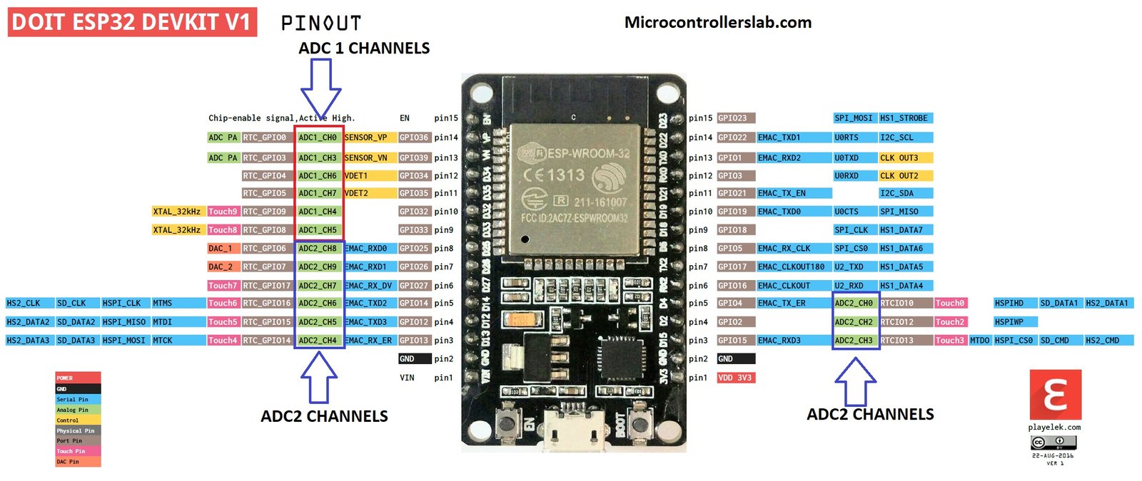
A critical point mentioned in the article is the conflict between ADC2 and Wi-Fi.
If you are using Wi-Fi, the Wi-Fi driver takes over ADC2. Therefore, if your application requires both Wi-Fi and analog readings, you must use GPIOs connected to ADC1.
2. Configuring the ADC's Input Range
The default input voltage range of the ADC might not match the output range of your sensor. The ESP32 provides two primary mechanisms to handle this: internal attenuation for adjusting the ADC's measurable range, and external voltage dividers for scaling down sensor voltages that exceed the ESP32's limits.
Attenuation
Attenuation is like changing the sensitivity of the ADC. It allows you to configure the full-scale voltage that corresponds to the maximum digital value (4095). By setting the attenuation, you can make the ADC accurately measure voltages higher than its default range.
The ESP-IDF provides four attenuation levels:
ADC_ATTEN_DB_0: No attenuation (approx. 0-1.1V range).ADC_ATTEN_DB_2_5: 2.5 dB attenuation (approx. 0-1.5V range).ADC_ATTEN_DB_6: 6 dB attenuation (approx. 0-2.2V range).ADC_ATTEN_DB_11: 11 dB attenuation (approx. 0-3.3V range).
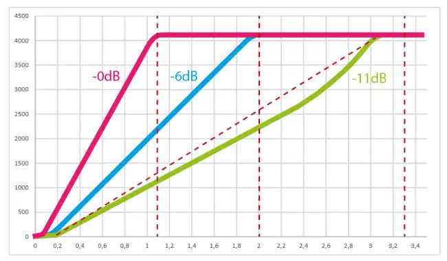
Choosing the right attenuation is crucial. You should select the setting that provides the smallest range that can still fully encompass your sensor's maximum output voltage. This maximizes the measurement resolution. For example, if your sensor outputs a maximum of 1.2V, ADC_ATTEN_DB_2_5 would be a better choice than ADC_ATTEN_DB_11.
Voltage Dividers
What if your sensor outputs a voltage higher than 3.3V, such as a common 5V sensor? Connecting this directly to an ESP32 GPIO pin will damage the chip. In this scenario, you must scale the voltage down externally using a voltage divider. As a mechanical engineer, you're familiar with scaling and dividing signals; this is the electronic equivalent. A voltage divider is a simple circuit made of two resistors that reduces a voltage by a fixed ratio.
Arduino ADC Explained: Using Analog Sensors for Your Gauges
This video from Garage Tinkering provides an excellent, practical explanation of why and how to use a voltage divider to safely interface a 5V sensor with an ESP32.
Watch from 11:36 to 15:00. The presenter explains the need for voltage scaling and walks through the calculation to select the correct resistor values to scale a 5V signal down to the ESP32's safe input range.
The key formula for a voltage divider is:
Your goal is to choose R1 and R2 such that is within the ESP32's measurable range (e.g., 0-3.3V) when is at its maximum.
3. Reading Values: From C API to C++ Wrapper
The ESP-IDF provides a C API for ADC operations. The most common and straightforward method is the One-Shot mode, where you request a single ADC reading when you need it. Let's look at the basic steps using the C API, which will form the foundation for our C++ class.
Based on the Random Nerd Tutorials article you reviewed, the process is:
- Initialize the ADC unit: Create a configuration struct (
adc_oneshot_unit_init_cfg_t) and calladc_oneshot_new_unit(). - Configure the ADC channel: Create another configuration struct (
adc_oneshot_chan_cfg_t) specifying the bit width and attenuation, then calladc_oneshot_config_channel(). - Read the value: Call
adc_oneshot_read()with the channel handle to get the raw integer value.
While this C API is functional, it's not very object-oriented. In keeping with the goals of this course, we'll wrap this functionality in a C++ class to provide a cleaner and more reusable interface.
Basic ESP32 ADC C++ library - EmbeddedTutorials
This tutorial from EmbeddedTutorials.com demonstrates how to create a C++ class to handle ADC readings, encapsulating the underlying ESP-IDF C functions. This is the same approach we took for the LEDC peripheral in the last lesson.
Study the sections describing the header file (analogio.h) and the implementation file (cppadc.cpp). Pay attention to: How the class stores ADC configuration (channel, bit width, attenuation) as private members. The implementation of SetChannel, SetBitWidth, and SetAttenuation. The GetRaw() method, which simply calls adc1_get_raw(). The GetVoltage() method, which uses the esp_adc_cal functions to convert the raw value to a more accurate millivolt reading. This calibration is an important feature for improving accuracy.
The C++ wrapper provides two key benefits:
- Encapsulation: It hides the complex ESP-IDF configuration structs and function calls behind a simple, intuitive interface.
- Calibration: It elegantly integrates the
esp_adc_callibrary, which uses factory-calibrated values stored in the ESP32's eFuse to correct for the ADC's non-linearity, providing a much more accurate voltage reading than simple linear mapping.
4. Converting a Raw Value to a Physical Unit
Getting a raw value (0-4095) or even a calibrated voltage is only part of the job. The final goal is to convert this measurement into a meaningful physical quantity, like pressure in PSI, temperature in Celsius, or distance in meters. This requires a mathematical formula, which is usually found in the sensor's datasheet.
The process typically involves a few steps of linear scaling and conversion.
Arduino ADC Explained: Using Analog Sensors for Your Gauges
Let's return to the Garage Tinkering video. The presenter does a fantastic job of walking through the entire mathematical derivation to convert a raw ADC reading into a final PSI value, accounting for the voltage divider and the sensor's characteristics.
Watch from 27:30 to 33:38. Follow the logic as the presenter goes from the raw ADC value, relates it to the original 5V sensor scale, applies the sensor's formula, and simplifies it all into a single, efficient equation.
Let's summarize the general process shown in the video:
-
Convert Raw ADC to Voltage: First, determine the voltage measured by the ADC. The simplest way is a linear mapping:
whereV_refis the ADC's reference voltage (e.g., 3.3V) andmax_raw_valueis the max reading (e.g., 4095 for 12-bit). Using theesp_adc_callibrary as shown in theGetVoltage()method is a more accurate way to do this. -
Account for Voltage Divider (if used): If you used a voltage divider to scale down the sensor's voltage, you must now scale the measured voltage back up to find the sensor's original output.
-
Apply Sensor Formula: Use the formula from the sensor's datasheet to convert to the physical unit. For example, a temperature sensor might have a linear relationship like:
As demonstrated in the video, you can often combine these steps into a single, more computationally efficient formula for your code.
Test your understanding!
You are using a pressure sensor that outputs 0.5V at 0 kPa and 4.5V at 1000 kPa. You have connected it to the ESP32's ADC, which is configured with 12-bit resolution and an attenuation that gives it a 0V to 3.3V measurement range. To interface the sensor, you used a voltage divider that halves the voltage (R1=R2).
What is the approximate raw ADC value you would expect to read at 500 kPa?
Show answer
-
Sensor Voltage at 500 kPa: Since the sensor is linear, 500 kPa is halfway through its range. The voltage is the midpoint between 0.5V and 4.5V, which is (0.5 + 4.5) / 2 = 2.5V.
-
Voltage at ADC Pin: The voltage divider halves the sensor voltage. So, the voltage at the ADC pin is 2.5V / 2 = 1.25V.
-
Raw ADC Value: Now, we map this voltage to the 12-bit ADC range (0-4095 for 0-3.3V).
So, you would expect a raw reading of approximately 1551.
Conclusion
You have now learned how to interface the analog world with your ESP32. By configuring and reading from the ADC, you can build systems that are aware of their environment, which is the first step in creating any intelligent device.
Key Takeaways:
- The ADC converts a continuous analog voltage into a discrete digital number.
- The ESP32's ADC has 12-bit resolution (0-4095) but exhibits non-linearity, which can be partially corrected with factory calibration.
- ADC1 channels should be used if your application also uses Wi-Fi.
- Attenuation configures the ADC's internal voltage measurement range, while external voltage dividers are needed for sensors with outputs greater than 3.3V.
- Wrapping the ESP-IDF C API in a C++ class provides a clean, reusable, and stateful interface for ADC operations.
- The final step is always to convert the raw ADC reading into a meaningful physical unit using a formula derived from the sensor's datasheet and your circuit's configuration.
In our next lesson, we will briefly cover the final piece of the ESP32's basic analog I/O capabilities: the Digital-to-Analog Converter (DAC), which allows you to output a true analog voltage.