Hello! Welcome to your next lesson on mastering the ESP32 with C++.
In our last lesson, we explored GPIO interrupts, an efficient, event-driven way to handle inputs like button presses. This freed the CPU from the inefficient task of polling. Today, we'll turn our attention from digital inputs to analog-style outputs by exploring one of the most versatile peripherals on the ESP32: the LEDC (LED Control) peripheral.
While its name suggests it's just for LEDs, the LEDC is a powerful Pulse-Width Modulation (PWM) generator. PWM is a fundamental technique in mechanical and electrical engineering for controlling devices like motors, heaters, and of course, dimming LEDs. This lesson will teach you how to configure and generate PWM signals, a skill that is crucial for building sophisticated mechatronic systems.
1. What is Pulse-Width Modulation (PWM)?
You know that a digital GPIO pin can only be in two states: HIGH (e.g., 3.3V) or LOW (0V). But what if you need a voltage in between? For example, to run a DC motor at half speed or set an LED to 25% brightness. This is where PWM comes in.
PWM simulates an analog voltage by switching a digital pin on and off very quickly. The key is to control the proportion of "on-time" to "off-time" within a fixed period. This proportion is called the duty cycle.
- 0% duty cycle: The signal is always off (0V average).
- 50% duty cycle: The signal is on for half the time and off for the other half (1.65V average).
- 100% duty cycle: The signal is always on (3.3V average).
To most devices, like an LED or a motor, this rapid switching looks like a steady, continuous voltage. By changing, or modulating, the pulse width, we can control the average voltage and thus control the device's behavior.
ESP32 with ESP IDF #3 | Controlling PWM Output with LEDC peripheral and use it to rotate a servo
For a quick visual recap of PWM and an introduction to how the ESP32 handles it with the LEDC peripheral, watch the first two minutes of this video from ltkdt.
Watch from 00:11 to 02:06. The video quickly explains the concept of duty cycle and introduces the two main parts of the LEDC peripheral: timers and channels.
2. The ESP32 LEDC Peripheral
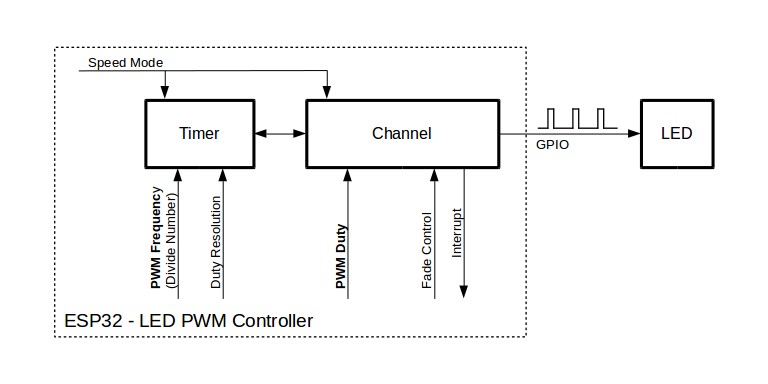
The ESP32 has a dedicated hardware peripheral, the LEDC, for generating up to 16 independent PWM signals. To configure it, you need to understand its two main building blocks: Timers and Channels.
-
LEDC Timers (4 available): A timer is the "heartbeat" of the PWM signal. It doesn't generate an output itself; instead, it defines the frequency of the PWM signal and the duty cycle resolution. The resolution determines how many steps of control you have over the duty cycle (e.g., 8-bit resolution gives 256 steps, 10-bit gives 1024 steps).
-
LEDC Channels (16 available): A channel is the link between a timer and a physical GPIO pin. Each channel is configured to:
- Use a specific timer as its source.
- Output the PWM signal on a specific GPIO pin.
- Generate a signal with a specific duty cycle.
The overall workflow, as outlined in the official ESP-IDF documentation, is:
- Configure a Timer: Set the desired frequency and duty resolution.
- Configure a Channel: Associate the channel with the configured timer and assign it to an output pin.
- Change the Duty Cycle: Update the channel's duty cycle to control the output.
3. Configuring LEDC with the ESP-IDF C API
Before we build a C++ wrapper, let's understand the underlying ESP-IDF functions. This knowledge is essential for debugging and for appreciating the abstraction that C++ provides.
Step 1: Timer Configuration
You configure a timer using the ledc_timer_config() function, which takes a pointer to a ledc_timer_config_t struct.
ledc_timer_config_t ledc_timer = {
    .speed_mode       = LEDC_LOW_SPEED_MODE,
    .duty_resolution  = LEDC_TIMER_10_BIT,
    .timer_num        = LEDC_TIMER_0,
    .freq_hz          = 5000, // 5 kHz
    .clk_cfg          = LEDC_AUTO_CLK
};
esp_err_t err = ledc_timer_config(&ledc_timer);
.duty_resolution: The number of bits for the duty cycle value.LEDC_TIMER_10_BITmeans the duty can range from 0 to 1023..freq_hz: The PWM signal frequency in Hertz.- Trade-off: Frequency and duty resolution are inversely related. The hardware has a finite clock speed. If you want a very high frequency, you must accept a lower resolution, and vice-versa. For dimming an LED, 5 kHz is fine. For audio or high-speed motor control, you might need a higher frequency.
Step 2: Channel Configuration
Next, you configure a channel with ledc_channel_config(), passing it a ledc_channel_config_t struct.
ledc_channel_config_t ledc_channel = {
    .gpio_num   = 25,
    .speed_mode = LEDC_LOW_SPEED_MODE,
    .channel    = LEDC_CHANNEL_0,
    .timer_sel  = LEDC_TIMER_0,
    .duty       = 0, // Initial duty cycle
    .hpoint     = 0
};
esp_err_t err = ledc_channel_config(&ledc_channel);
.gpio_num: The pin that will output the signal. Not all pins can be used for PWM..channel: Which of the 16 hardware channels to use..timer_sel: Which timer to use as the source. Its speed mode must match the channel's speed mode.

Step 3: Updating the Duty Cycle
Once configured, you can change the PWM output at any time. This is a two-step process:
ledc_set_duty(speed_mode, channel, duty_value): Sets the new duty cycle in the channel's register. Theduty_valueis an integer based on the resolution (e.g., 0-1023 for 10-bit).ledc_update_duty(speed_mode, channel): Atomically applies the new duty cycle setting.
For example, to set a 25% duty cycle on a channel with 10-bit resolution:
// 10-bit resolution gives a max value of 2^10 - 1 = 1023
uint32_t duty_25_percent = (uint32_t)(0.25 * 1023); // = 255

ledc_set_duty(LEDC_LOW_SPEED_MODE, LEDC_CHANNEL_0, duty_25_percent);
ledc_update_duty(LEDC_LOW_SPEED_MODE, LEDC_CHANNEL_0);
4. A C++ Wrapper for the LEDC Peripheral
Using the C API directly works, but it's verbose and requires you to manage state across multiple function calls. As you aim to master C++ for the ESP32, wrapping this functionality in classes is a natural and powerful step. This encapsulates the configuration details and provides a clean, reusable interface.
We'll study a tutorial that creates two classes: CppLedcTimer and CppLedc.
ESP32 LEDC library with ESP-IDF C++
This tutorial from EmbeddedTutorials.com provides an excellent walkthrough of creating C++ classes to manage the LEDC timers and channels, encapsulating the C API we just discussed.
Study the sections 'Define the LEDC and Timer classes in the header' and 'Implement the LEDC and Timer Class methods'. As you read, focus on: How the ledc_timer_config_t and ledc_channel_config_t structs are used as private members of the C++ classes. How the public methods (like SetTimerFrequency or SetChannelDutyCycle) provide a clean interface that calls the underlying ESP-IDF C functions (ledc_timer_config, ledc_set_duty, etc.). The logic in the SetChannelDutyCycle method, which is the primary function you'll use to dynamically control the PWM output.
The approach in the tutorial is a great example of object-oriented design in an embedded context:
-
Encapsulation: The complex
structs and multi-step configurations are hidden inside the class implementations. The user of the class only needs to call intuitive methods likeLedcTimer0.SetTimerDutyResolution(...)orLEDC.SetChannelGpio(...). -
State Management: The configuration for a timer or channel is stored within its corresponding object, making the code much easier to reason about, especially when using multiple PWM outputs.
-
Readability: Compare the C-style setup with the C++ version from the tutorial's
main.cpp:// In setup() LedcTimer0.InitializeDefaults(); LedcTimer0.SetTimerDutyResolution(LEDC_TIMER_8_BIT); LEDC.SetChannelGpio(25); // In run() loop LEDC.SetChannelDutyCycle(i);This is significantly cleaner and more expressive.
Test your understanding!
You need to generate a PWM signal for a servo motor, which typically requires a 50 Hz frequency. You decide to use 12-bit resolution for fine control. You've created a CppLedcTimer object called servoTimer. Which two method calls would you make on servoTimer to configure it correctly?
Show answer
You would need to set both the frequency and the duty resolution.
servoTimer.SetTimerFrequency(50);servoTimer.SetTimerDutyResolution(LEDC_TIMER_12_BIT);
5. Practical Application: Fading an LED
Let's put this all together with a practical example: making an LED smoothly fade in and out. This requires continuously updating the PWM duty cycle from 0% to 100% and back again. The tutorial you just reviewed provides a perfect implementation.
ESP32 LEDC library with ESP-IDF C++
Now let's see how the C++ classes are used in a complete application. This final part of the tutorial shows the main application code.
Read the section 'USE LEDC to control the brightness of an LED'. Pay close attention to the code in main.h and main.cpp. Notice how objects for the timer and channel are declared, configured in setup(), and then manipulated inside a for loop in run() to create the fading effect.
The core of the fading logic is simple yet effective:
// Increasing brightness
for(int i = 0; i < 255; i++) {
    LEDC.SetChannelDutyCycle(i); // Using the C++ wrapper class
    vTaskDelay(1);
}

// Decreasing brightness
for(int i = 255; i > 0; i--) {
    LEDC.SetChannelDutyCycle(i);
    vTaskDelay(1);
}
This demonstrates how easy it becomes to control the PWM output once the underlying hardware is abstracted away by your C++ classes.
Conclusion
You have now learned how to generate and control PWM signals, a cornerstone of embedded systems programming. This technique opens the door to controlling a vast array of analog devices, from simply dimming lights to implementing sophisticated speed control for motors.
Key Takeaways:
- PWM is a digital technique to simulate an analog output by varying the signal's duty cycle.
- The ESP32's LEDC peripheral is used for PWM generation and is configured using Timers and Channels.
- Timers set the signal's frequency and duty resolution. These two parameters have an inverse relationship.
- Channels link a timer to a GPIO pin and control the signal's duty cycle.
- Wrapping the ESP-IDF C API in C++ classes leads to cleaner, more maintainable, and reusable code, which is a key goal of this course.
In our next lesson, we will look at the other side of the analog world: reading analog inputs. We will learn to configure and use the ESP32's Analog-to-Digital Converter (ADC) to read continuous voltage levels from sensors. Combining ADC inputs with PWM outputs is how you build closed-loop control systems.