Recommended resources
The freely available resources this lesson will direct you to.
Hello! Welcome to your tenth lesson.
In our last session, we explored the nature of power in AC circuits with pure sine waves, distinguishing between the fluctuating instantaneous power and the net, useful average power. We ended with a crucial observation: most real-world signals, especially in digital systems, are not perfect sinusoids.
This lesson directly addresses that point. We'll tackle the learning outcome: Conceptually explain how complex periodic waveforms can be viewed as a sum of simple sinusoidal harmonics.
You have an interest in low-level computing and electronics, where signals like square waves (clock signals, data lines) are fundamental. This lesson will provide the conceptual framework for understanding the "hidden" sinusoidal nature of these signals. We won't be doing the heavy math of calculating coefficients, but will instead focus on the core intuition, which is that any repeating waveform can be built by adding together a set of simpler sine waves. This powerful idea is known as the Fourier series.
1. The Big Idea: Building Complexity from Simplicity
Let's start with the most common non-sinusoidal signal in electronics: the square wave. At first glance, it seems completely different from a smooth sine wave. Yet, it can be constructed by adding sine waves together.
The following video provides an excellent, step-by-step visual demonstration of this process.
Intro to FOURIER SERIES: The Big Idea
Watch this video, 'Intro to FOURIER SERIES: The Big Idea' by Dr. Trefor Bazett. It masterfully shows how adding more sine waves of specific frequencies and amplitudes gets you closer and closer to a perfect square wave.
Watch from the beginning to 05:30. Focus on the visual intuition. Notice how each new sine wave that is added helps to flatten the peaks and steepen the sides of the previous approximation.
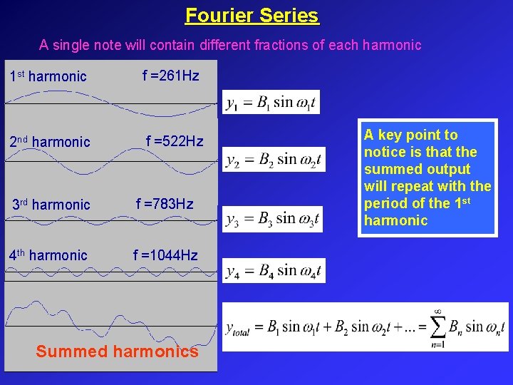
As you saw, the process starts with a sine wave that has the same period as the square wave. This is called the fundamental frequency or the 1st harmonic.
Then, we add other sine waves with frequencies that are integer multiples of the fundamental (e.g., 3 times, 5 times, 7 times, etc.). These are the harmonics. For a perfect square wave, it turns out we only need the odd harmonics.
2. A Deeper Intuition: From Heat Flow to Drawing with Circles
The idea of breaking down signals into sine waves was developed by Joseph Fourier while studying how heat flows. It's a concept that is surprisingly universal. The next video from 3Blue1Brown, a channel known for its deep and beautiful mathematical visualizations, will give you a more abstract and powerful mental model for this concept.
But what is a Fourier series? From heat flow to drawing with circles | DE4
This video, 'But what is a Fourier series? From heat flow to drawing with circles,' connects the idea of summing sine waves to an elegant visual of rotating vectors, or 'epicycles.' This will appeal to your interest in abstract and computational thinking.
Watch the first 6 minutes and 26 seconds (00:00 - 06:26). Don't worry about the heat equation details. Focus on two key ideas: 1) the stunning visual of how adding simple rotations can create a complex drawing, and 2) Fourier's 'absurd' and brilliant question: can any function, even a discontinuous one like a step function, be expressed as a sum of sine waves?
The key insight from the video is that this isn't just a clever approximation; in the limit, the infinite sum of sine waves can become the complex waveform. The simple, smooth, and continuous sine waves conspire to create a flat, discontinuous square wave.
3. Practical Implications in Electronics
This concept is not just a mathematical curiosity; it has profound, practical consequences in electronics and computer engineering. Thinking of a square wave in terms of its constituent harmonics is essential for designing high-speed digital systems.
The following article, written from a very practical engineering perspective, makes this connection beautifully.
Square waves, or non-elephant biology
Read the following article 'Square waves, or non-elephant biology' by lcamtuf. It directly explains the harmonic content of a square wave and shows what it looks like on a real instrument, an oscilloscope.
Read the first two sections of the article. Start from the beginning and read down to the paragraph just before the one that begins 'To illustrate the qualitative worth of this approach...'. Pay close attention to the formula for the square wave, the plots showing the progressive approximation, and the image of the FFT (Fast Fourier Transform) from an oscilloscope. The FFT is the tool that performs this decomposition in practice.
The article highlights a critical point: a "1 MHz square wave" is not just a 1 MHz signal. It is a 1 MHz fundamental plus a 3 MHz harmonic, a 5 MHz harmonic, a 7 MHz harmonic, and so on.
Why does this matter?
- Signal Integrity: If you pass a 1 MHz square wave through a wire or circuit that can't handle high frequencies, it might attenuate (reduce) the higher harmonics. This will round off the sharp edges of your square wave, potentially causing errors in a digital system.
- Filtering: Sometimes harmonics are unwanted noise. For example, a switch-mode power supply generates a noisy output full of harmonics. Engineers design filters specifically to remove these harmonics and produce clean DC voltage.
- Electromagnetic Interference (EMI): The sharp edges of a fast-switching square wave, rich in high-frequency harmonics, can act like a radio antenna, broadcasting noise that can interfere with other nearby electronics.
4. Interactive Exploration
To solidify your intuition, it helps to play with the concept yourself. The following interactive guide lets you see how adding more terms to the Fourier series improves the approximation of a square wave.
An interactive guide to Fourier series
The web page 'An interactive guide to Fourier series' provides a great hands-on visualization. We will focus on the square wave example.
Scroll down to the section titled 'Decomposing periodic functions.' Find the interactive graph with the slider that lets you alter the number of terms used to approximate a square wave. Move the slider back and forth and observe how the red curve (the approximation) gets closer to the gray curve (the ideal square wave) as you add more terms. This directly visualizes the concept we've been discussing.
Notice the small overshoots that remain near the sharp edges, even with many terms. This is a real phenomenon known as the Gibbs phenomenon. It's a reminder that we are dealing with an infinite series, and any finite number of terms will be an approximation.
Conclusion
In this lesson, we have built a conceptual understanding of one of the most important ideas in signal analysis. We moved from the pure sine waves of our last lesson to the complex periodic waves that are common in the real world.
Key Takeaways:
- Any periodic waveform can be decomposed into, or built from, a sum of simple sine waves. This is the principle of the Fourier series.
- The component with the same frequency as the complex wave is the fundamental or 1st harmonic.
- The other components, which have frequencies that are integer multiples of the fundamental, are the harmonics (2nd, 3rd, 4th, etc.).
- The shape of the complex waveform is determined by which harmonics are present and what their amplitudes are. A square wave, for example, is composed of its fundamental and all odd harmonics.
- This concept is critical in electronics for understanding signal integrity, filtering, and interference in systems that use non-sinusoidal signals like square waves.
Preview of the Next Lesson:
We've spent the last few lessons analyzing the characteristics of AC signals. Now, we will shift our focus back to a core theme of the course: energy conversion. In the next lesson, we will explore the fundamental principles of how electrical energy is converted into mechanical motion, beginning with the operating principles of a DC motor. We will see how the concepts of voltage, current, and energy that we've been studying come together in this practical application.