Recommended resources
The freely available resources this lesson will direct you to.
Hello! Welcome to our ninth lesson.
In our last session, we established a language for describing time-varying signals, defining the key parameters of amplitude, frequency, period, and phase. We saw how a sinusoidal voltage or current can be precisely described by the equation .
This naturally leads to a critical question: how do we determine the power in a circuit where voltage and current are constantly changing? In DC circuits, power was a simple, constant value, . In AC circuits, the concept is more nuanced. This lesson will explore that nuance by addressing the learning outcome: Explain the difference between instantaneous and average power for time-varying signals.
Following your preference for building strong physical intuition, we will first visualize what "power" means moment-to-moment, and then use that understanding to define the concept of average power, which represents the net energy that does useful work.
1. Instantaneous Power: A Moment-to-Moment Perspective
The fundamental definition of electrical power remains the same in AC circuits as it was in DC: power is the product of voltage and current. However, since voltage and current are now functions of time, power is also a function of time. We call this instantaneous power, .
This means the power delivered to a component is changing from one moment to the next.
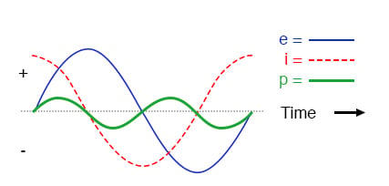
- If at a certain instant, both and are positive (or both are negative), their product is positive. This means energy is flowing from the source to the load.
- If at a certain instant, and have opposite signs, their product is negative. This is a new and crucial concept: it means energy is flowing back from the load to the source.
The following video provides an excellent visual introduction to this idea.
Why is Instantaneous Power Flow Important?
The video 'Why is Instantaneous Power Flow Important?' by Iain Explains Signals, Systems, and Digital Comms, clearly demonstrates how instantaneous power is calculated and what it means when the power waveform goes negative.
Watch from the beginning to 03:44. Pay close attention to how the instantaneous power waveform is generated by multiplying the voltage and current waveforms, and the explanation for the periods of negative power.
As the video highlighted, the phase difference between voltage and current is the key factor that determines the shape of the instantaneous power waveform.
2. Deconstructing Power: The Average and Fluctuating Components
To better understand the implications of this fluctuating power, we can use a trigonometric identity to break down the instantaneous power equation into a more insightful form.
Let's assume the voltage and current are sinusoidal with a phase difference of :
Then the instantaneous power is:
Using the identity , we can rewrite this as:
This revised equation is extremely revealing. It shows that instantaneous power is the sum of two distinct parts:
- A constant, time-independent term: This is the average power, often denoted as or simply . This is the "DC component" or offset of the power waveform. It represents the net, unidirectional transfer of energy over a full cycle. This is the power that does useful work, like generating heat in a resistor or producing torque in a motor.
- A sinusoidal term that fluctuates at twice the original frequency (): This component represents energy that is exchanged back and forth between the source and the load. Its average value over a full cycle is zero. This "sloshing" of energy is also known as reactive power.
The following reading walks through this derivation and its implications clearly.
Sinusoidal Steady State Power & Average Power
The article 'Sinusoidal Steady State Power & Average Power' on EEPower provides a clear mathematical breakdown of instantaneous power into its average and sinusoidal components.
Read the sections 'Calculating Instantaneous Power' and 'Average and Sinusoidal Power'. Focus on how the final equation for P(t) is split into two components and the physical meaning attributed to each.
3. Physical Intuition: Resistors vs. Reactive Components
Your preference for physical intuition is especially valuable here. Let's examine what this decomposition of power means for different types of components. We can use the concept of "energy boxes" from the following video to build a strong mental model.
The video 'Real vs Reactive Power' by Eugene Khutoryansky provides a powerful visual analogy for understanding how phase shift affects net energy flow.
Watch from the beginning to 02:45. Notice how the 'energy boxes' are delivered when voltage and current are in-phase, but just slosh back and forth when they are 90 degrees out-of-phase.
Let's apply this intuition to our power equation by considering two extreme cases.
Case 1: Purely Resistive Load ()
For a resistor, voltage and current are perfectly in-phase.
- Mathematically: With , . The average power is at its maximum value: . The instantaneous power is . This value is always positive or zero, never negative.
- Physically: The resistor continuously dissipates energy as heat. It never returns energy to the source. The "energy boxes" are all delivered and consumed.
Case 2: Purely Reactive Load (e.g., ideal Inductor or Capacitor, )
For an ideal inductor or capacitor, voltage and current are 90 degrees out-of-phase.
- Mathematically: With , . The average power is zero. The instantaneous power becomes purely sinusoidal: . It fluctuates symmetrically around zero.
- Physically: These components store energy (in a magnetic or electric field) and then return it fully to the source on the next half-cycle. There is no net energy consumption. The "energy boxes" are delivered to the load and then sent right back.
The following document provides a concise summary and clear graphs for the power in resistors, inductors, and capacitors.
Module 3: Analysis of AC circuits
These slides from a university course provide a compact summary of instantaneous power for different components.
Review the slides titled 'Instantaneous power of a resistor', 'Instantaneous power of an inductor', 'Instantaneous power of a capacitor', and 'Power absorbed vs. power exchanged'. Observe how the power waveforms and remarks confirm our two cases.
The crucial insight here is that even when the average power is zero, the instantaneous power can be very large. This means large currents can be flowing and significant voltages can be present, which must be accounted for in circuit design (e.g., wire thickness, component ratings), even if no useful work is being done.
Summary: The Key Differences
Let's consolidate our understanding.

| Instantaneous Power | Average Power |
|---|---|
| The value of power at a specific moment in time. | The net power delivered over one or more full cycles. |
| Calculated as . | Calculated as the time average of , or . |
| Varies continuously over a cycle, oscillating at twice the frequency of the voltage/current. | A constant value. |
| Can be positive (power absorbed by load) or negative (power returned to source). | Always positive or zero for passive loads. Represents the power that is truly consumed (e.g., converted to heat). |
| Describes the full picture of energy exchange, including the "sloshing" of energy in reactive components. | Describes only the net, useful transfer of energy. |
Conclusion
In this lesson, we dissected the concept of power in AC circuits, distinguishing between the moment-to-moment instantaneous power and the overall net energy transfer represented by average power.
Key Takeaways:
- Instantaneous power is the product of instantaneous voltage and current, , and represents the rate of energy transfer at any given moment.
- Due to phase shifts, can become negative, indicating that energy is being returned to the source from the load.
- Average power is the constant component of the instantaneous power waveform. It represents the net power that is consumed by a circuit to do useful work.
- The difference between voltage and current phase, , is critical: it determines how much of the instantaneous power contributes to the average power versus how much is simply exchanged back and forth. A purely resistive circuit () is most effective at converting electrical energy, while a purely reactive circuit () consumes zero net energy.
Preview of the Next Lesson:
We've based our analysis today on perfect, single-frequency sine waves. However, many real-world signals (like the output of a power supply or the signal in a digital system) are more complex periodic waveforms. In our next lesson, we will explore how these complex waves can be understood as a sum of simple sinusoids, a concept known as harmonics. Our understanding of power will be essential as we consider the power content of these more complex signals.