Recommended resources
The freely available resources this lesson will direct you to.
Hello! Welcome to your eleventh lesson.
In our last lesson, we took a conceptual dive into Fourier series, discovering that complex periodic waveforms, like the square waves in digital systems, are composed of simple sine waves. This was a detour into the frequency domain. As promised, we now return to our core theme of energy, applying the circuit principles we've learned to a tangible device.
This lesson addresses the learning outcome: Explain the operating principle of a DC motor based on the conversion of electrical energy to mechanical energy via electromagnetic forces.
Your interest in low-level computing and embedded systems makes this topic particularly relevant. Microcontrollers often interface directly with motors to create motion. Understanding how a motor works isn't just an exercise in physics; it's foundational knowledge for robotics and control systems. We will build the concept from the ground up, focusing on the physical intuition behind each part of the process.
1. The Fundamental Link: Electricity and Magnetism
The entire operation of a DC motor hinges on a simple principle: electric current creates a magnetic field. A normal "permanent" magnet is always on, but a magnet made by running current through a coil of wire—an electromagnet—can be turned on and off, and most importantly, its polarity (which end is North and which is South) can be flipped by reversing the current direction.
This ability to control a magnetic field with electricity is the key to converting electrical energy into mechanical force.
Let's watch a video that brilliantly animates this foundational concept.
How does an Electric Motor work? (DC Motor)
The video 'How does an Electric Motor work? (DC Motor)' by Jared Owen provides an exceptionally clear, animated walkthrough. We'll start by focusing on how an electromagnet is made and how it interacts with a permanent magnet to produce force.
Watch from 02:27 to 04:29. First, you'll see how wrapping a wire around a bolt and passing current through it creates a controllable electromagnet. Then, the video demonstrates the core principle of rotation: by repeatedly reversing the polarity of this electromagnet, it can be made to continuously spin within the field of a permanent magnet.
The video shows that by manually switching the wires, you can create a continuous "push-pull" force that results in rotation. The north pole of the electromagnet is repelled by the north pole of the outer magnet and attracted to the south pole. Once it aligns, if we could instantly flip the electromagnet's polarity, it would be repelled again and continue to turn.
The obvious challenge is: how do you automate this polarity switching?
2. The Mechanical Solution: The Commutator
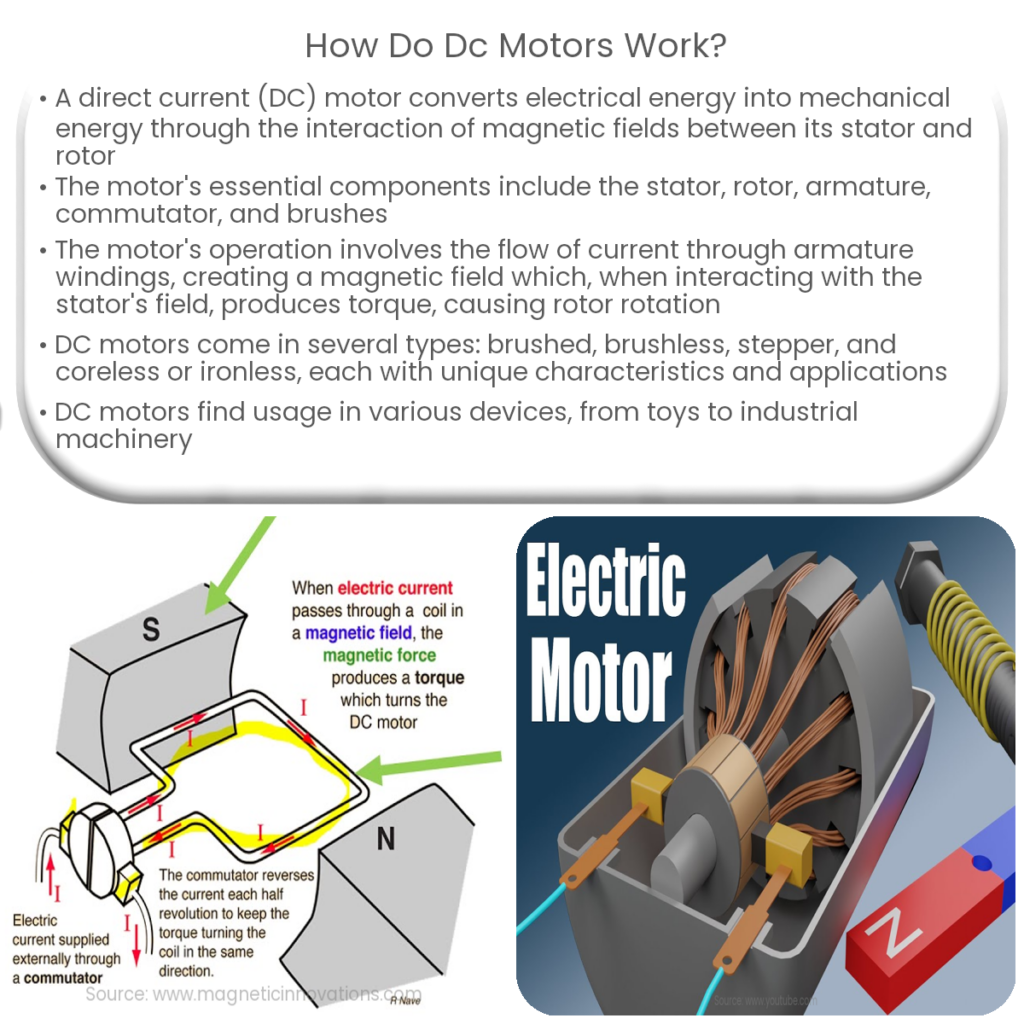
Manually flipping wires isn't practical. A real DC motor needs a mechanism to automatically reverse the current direction in the spinning coil at the perfect moment. This is the ingenious role of the commutator and brushes.
Let's continue with the same video to see how this works.
How does an Electric Motor work? (DC Motor)
Now we'll see the clever mechanical solution that allows the motor to spin continuously on its own.
Watch from 04:29 to 06:09. Pay close attention to how the commutator (the split ring) rotates with the coil (the armature) and how the brushes (the stationary contacts) provide power. Notice the moment the brushes cross the gap in the commutator—this is the instant the current direction in the coil is reversed.
This is the heart of the DC motor's design:
- The Stator: The stationary part, which consists of the permanent magnets that create a constant magnetic field.
- The Rotor (or Armature): The rotating part, which is the coil of wire that becomes an electromagnet when current flows through it.
- The Commutator: A split ring attached to the rotor that reverses the direction of the current in the coil every half-turn.
- The Brushes: Stationary carbon blocks that make contact with the spinning commutator, delivering power from the battery to the coils.
3. A Formal Tool for Predicting Force: Fleming's Left-Hand Rule
We now have an intuitive feel for how the motor works. To make our understanding more precise, we can use a formal rule to determine the direction of the force on the wire. This is Fleming's Left-Hand Rule.
It relates three quantities, which we assign to our thumb, index finger, and middle finger:
- Thumb: The direction of the Thrust or Force.
- Forefinger (Index): The direction of the magnetic Field (from North to South).
- Center finger (Middle): The direction of the Current (using conventional current, from + to -).
Let's see this rule explained and applied.
How does an Electric Motor work? DC Motor explained
The video 'How does an Electric Motor work? DC Motor explained' from The Engineering Mindset introduces Fleming's Left-Hand Rule and shows how it applies to the wires in the motor's coil.
Watch from 09:17 to 11:57. The video provides a mnemonic for using the rule and then applies it to a single loop of wire to show why one side is pushed up while the other is pushed down, causing rotation.
By applying this rule, you can see that the forces on the opposite sides of the coil are in opposite directions, creating a turning force, or torque. When the commutator flips the current, the direction of the forces on each segment of the coil also flips, ensuring the torque always pushes the rotor in the same rotational direction.
4. The Complete Picture: Back EMF
We've focused on how electrical energy creates motion. But the story doesn't end there. There's a crucial feedback mechanism at play.
You already know from previous lessons that a changing magnetic field induces a voltage in a coil (Faraday's Law of Induction). As the motor's coil rotates within the magnetic field, it's essentially acting like a generator. It induces a voltage of its own!
Lenz's Law tells us that this induced voltage will oppose the change that created it. In this case, it opposes the original voltage from the battery that is driving the motor. This opposing voltage is called Back Electromotive Force (Back EMF).
Let's explore this concept through a short reading.
The article 'Back Emf' from College Physics explains this phenomenon clearly. It's the key to understanding how a motor behaves as part of an electrical circuit.
Read the first three sections of the article. Focus on understanding that back EMF is proportional to the motor's speed and that it subtracts from the supply voltage, determining the actual current the motor draws.
This concept of back EMF explains several key behaviors of DC motors:
-
High Startup Current: When the motor is first turned on, its speed is zero, so the back EMF is zero (). The only thing limiting the current is the coil's own small resistance (). According to Ohm's Law, the startup current is high: . This is why the lights in your house might dim for a moment when a large appliance like a refrigerator turns on.
-
Self-Regulation at Operating Speed: As the motor speeds up, the back EMF increases. This opposing voltage reduces the net voltage across the coil. The current drawn by the motor drops to . The motor settles at a speed where the torque produced is just enough to overcome the friction and the mechanical load.
-
Response to Load: If you put a heavy load on the motor (e.g., an electric wheelchair going up a hill), it slows down. This decrease in speed reduces the back EMF. The net voltage increases, causing the motor to draw more current. This increased current produces more torque to handle the heavier load. This is a beautifully elegant self-regulating system.
Conclusion
In this lesson, we have deconstructed the DC motor, revealing it to be a fascinating interplay of electrical and mechanical principles. We have seen how a simple physical law—that current creates a magnetic field—can be harnessed through clever engineering to produce continuous rotation.
Key Takeaways:
- A DC motor converts electrical energy to mechanical energy using electromagnetic forces.
- The core components are the stator (stationary permanent magnet) and the rotor (spinning electromagnet).
- The commutator and brushes work together as a mechanical switch to reverse the current in the rotor coils every half-turn, ensuring the torque is always applied in the same direction for continuous rotation.
- Fleming's Left-Hand Rule is a formal tool for predicting the direction of the force on a current-carrying wire in a magnetic field.
- A spinning motor also acts as a generator, producing a Back EMF that opposes the supply voltage. This back EMF is proportional to the motor's speed and is crucial for the motor's self-regulation of current and torque.
Preview of the Next Lesson:
We have just learned that a motor, when it spins, is also a generator. In the next lesson, we will explore this idea directly. We'll examine the operating principle of a DC generator, where the goal is the reverse: to convert mechanical energy (spinning the shaft) into electrical energy. You will see that the underlying physics is identical, just applied with a different goal in mind.