Recommended resources
The freely available resources this lesson will direct you to.
- How Diffraction Affects Your Photos and How to Fix It!www.youtube.com
- The Basics Of Diffraction and Airy Disks | How Sensors Out Resolve Lenses | Physics of Pixel Pitchwww.youtube.com
- [PDF] How to Measure MTF and other Properties of Lenses - Optikoswww.optikos.com
- Depth of Field in Depthcarlesmitja.net
Hello. Last lesson showed why opening a lens increases the light reaching an image. The same aperture also determines which rays form each image point. That creates a less obvious engineering trade-off: a small opening suppresses blur from imperfect focus, but makes wave diffraction more conspicuous.
This lesson quantifies both effects on the image plane. We will use an ideal circular-pupil thin lens so that the competition is visible without lens aberrations. The result will be an aperture choice for a specified focus error—not a universal “sharpest f-stop.”
A perfectly focused point still has a size
For an ideal lens, geometrical rays from a point at the chosen focus distance meet at one image point. Light is a wave, however, and the finite pupil limits the range of wavefront directions that can reach that point. With a circular, unobstructed pupil, the image is an Airy pattern: a bright central region surrounded by progressively weaker rings.
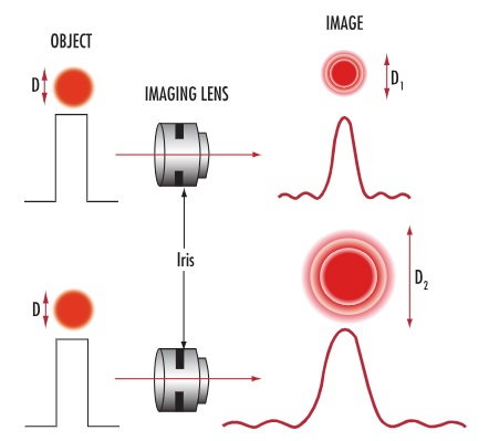
Let be the entrance pupil diameter, the image distance, and the wavelength. In the paraxial limit, the radius from the central maximum to the first dark ring is approximately
The Airy-disk diameter, measured to that first dark ring, is therefore
This uses the working f-number from the previous lesson. At distant focus , so . At close focus, substituting the nominal f-number without accounting for the larger image distance understates the diffraction scale.
For example, at and distant focus, f/8 gives , while f/16 gives . Stopping down by two stops halves the pupil diameter and doubles the Airy-disk diameter. More exposure time can replace the lost light, but it cannot restore the fine spatial structure suppressed by that narrower pupil.
Read the “Diffraction” subsection on pp. 26–27 of Jeff Conrad’s Depth of Field in Depth. It develops the Airy-disk diameter and distinguishes that diameter from the point separation used in the Rayleigh criterion. Follow
Read Jeff Conrad’s account to check the diffraction scale and the distinction between spot size and a resolution criterion.
In “Diffraction” (pp. 26–27), begin with the paragraph describing an ideal lens imaging a point as an Airy pattern. Read through the close-up comparison, stopping before “Combined Defocus and Diffraction.” Focus on why the formula contains both f-number and magnification, and why the Rayleigh separation is an Airy radius, not its diameter.
An Airy diameter is useful, but it is not a declaration that all finer detail disappears. Resolution depends on what counts as distinguishable and on the contrast of the detail being imaged. We will return to that distinction after calculating defocus.
A misplaced image plane produces a geometric circle
Suppose a particular subject point would come to focus at image distance , but the sensor is fixed at . At the sensor, the converging or diverging cone has a finite cross-section. Similar triangles give its geometric defocus-circle diameter:
Here describes the image-side cone for the subject point whose true focus is . The thin-lens equation determines that position from subject distance :
The geometry exposes the opposing aperture dependence. At a fixed focus error , reducing reduces the defocus circle in direct proportion. Equivalently, increasing f-number makes geometric defocus blur approximately proportional to , provided the focus geometry stays fixed.
Consider a lens with its sensor at , focused at infinity. A point away would instead focus at . At f/8, , so
At f/16, the pupil diameter is halved and the geometric circle is approximately . This is the physical basis of the familiar observation that stopping down makes objects away from the focus plane look sharper. It has not moved their true focus to the sensor; it has narrowed their ray cones.
A geometrical “circle” is not the complete intensity pattern recorded by a real camera. Even a perfectly focused point diffracts, and a defocused point difracts too. The geometric diameter is a useful measure of one contribution, not a diffraction-free image that can be observed separately.
Where stopping down ceases to help
For the point in our example, the diffraction diameter is approximately . Holding the focus error and wavelength fixed therefore gives two opposed trends:
The numerical scales make the trade-off concrete:
| Aperture | Geometric defocus diameter | Airy-disk diameter |
|---|---|---|
| f/8 | ||
| f/12 | ||
| f/16 | ||
| f/22 |
The two diameters become equal near f/12. To see why, write and define the fixed focus displacement . Equating the diameters gives
For these distances and , . This crossover identifies where the two chosen diameter measures are comparable. It does not, by itself, prove that every image-detail measure reaches its optimum there.
One convenient estimate of a combined blur width is a root-square model,
For fixed geometry, this has the form . Its minimum occurs when its two terms are equal, also near f/12 in the example. This is an engineering approximation, not an exact law for adding Airy patterns and defocus circles: their diameter conventions differ, and diffraction and defocus act together on the same wavefront.
Conrad examines that approximation under “Combined Defocus and Diffraction” (pp. 27–28), then derives an optimum under “Optimum f-Number” (p. 28). Read
Return to Conrad’s treatment for a documented example of a combined-blur model and its aperture optimum.
In “Combined Defocus and Diffraction” (pp. 27–28), start where the author states that both effects occur at every f-number. Continue through the optimum condition in “Optimum f-Number” (p. 28). Treat the root-square rule as a modeling choice rather than a fundamental optical identity.
The result also depends on which plane you care about. If , geometric defocus vanishes; for this ideal lens, stopping down only enlarges the diffraction pattern at that plane. If you need good detail across subjects at several distances, a moderate aperture may improve the out-of-focus regions even as it reduces the finest contrast at the focused plane. A real lens adds another consideration—aberrations that may improve when stopped down—which we will examine later.
Resolution means transferred contrast, not just spot diameter
A camera images extended patterns, not merely isolated points. For ordinary incoherent photographic imaging, the response to an ideal point is the point-spread function. Neighboring point responses overlap, reducing the contrast of fine patterns. The modulation transfer function, or MTF, reports how much contrast survives at each spatial frequency.
For an ideal, in-focus circular pupil, the diffraction-limited MTF reaches zero at the image-plane cutoff frequency
At distant focus and , that is approximately cycles/mm at f/8 and cycles/mm at f/16. Contrast declines before the cutoff; the cutoff is not a promise that frequencies just below it will appear strongly. It also describes the in-focus diffraction limit, not the contrast delivered by our defocused point.
The precise MTF of a defocused lens requires the pupil’s wavefront phase as well as its diameter. Consequently, a single blur width cannot tell us exactly which f-number best preserves, say, a specified band of image detail. Different spatial frequencies can have different optima. Nor should a signed optical transfer value below zero be called a negative MTF: MTF is its nonnegative magnitude; a negative signed response indicates contrast reversal.
For a closer look, read “Modulation Transfer Function” in Conrad (pp. 29–34). Begin with
Conrad’s MTF treatment shows what a blur-diameter estimate leaves out: contrast depends on spatial frequency, focus setting, and aperture together.
In “Modulation Transfer Function” (pp. 29–34), first read the opening motivation. Inspect Figure 6 and read the stopping-down explanation. Then compare Figures 7–10 using the figure discussion. You need not evaluate the defocused-MTF integral; focus on why the best aperture depends on the image detail of interest.
What to retain
For a circular pupil in this thin-lens model, diffraction gives an Airy-disk diameter : stopping down enlarges it. A focus displacement gives a geometric defocus diameter : stopping down shrinks it. Their crossover provides a useful aperture scale for a stated subject and focus setting, while an MTF criterion provides the more precise question: which detail, at which depth, must retain how much contrast?
Next lesson turns that focus-error geometry into depth of field and hyperfocal distance by specifying an acceptable circle of confusion. Today’s diffraction result will remain an important qualification: making that geometric circle smaller does not guarantee an indefinitely sharper photograph.