Recommended resources
The freely available resources this lesson will direct you to.
Hello. Last lesson established where a thin lens forms an image and how magnification changes its size. This lesson adds the missing radiometric question: how much optical power reaches that image, and how concentrated is it on the image plane? The answer distinguishes entrance pupil diameter, which controls the light admitted from a scene patch, from f-number, which largely controls the irradiance of its image.
We will work first with an on-axis, extended scene of specified radiance and an ideal thin lens in air. That model gives a useful camera equation and a precise meaning for optical throughput. We will then account for close focus and transmission losses.
The opening that the scene sees
An iris diaphragm is a physical opening inside a lens. Seen through any elements in front of it, however, that opening can appear magnified or reduced. Its optical image, viewed from the scene, is the entrance pupil. If its diameter is and the lens focal length is , the nominal f-number is
Thus a lens at f/4 has an entrance pupil diameter of . That does not necessarily mean its diaphragm blades form a physical opening, nor that its front element has that diameter.
For a visual account, watch the indicated portions of Aperture & f-stop Myths Debunked: The Importance of the Entrance Pupil, by Gerald Undone. Use the front and rear views to distinguish the entrance and exit pupils; treat looking through a lens as a way to understand the geometry, not as a precision measurement method.
Aperture & f-stop Myths Debunked: The Importance of the Entrance Pupil
The video makes visible why the pupil specified by an f-number need not equal the internal diaphragm opening.
Watch pupil definition for the view from each side of the lens, then lens examples for why optical magnification of the stop matters in telephoto and zoom designs.
In the following sketch, the source and image patches are viewed through different pupils. The labeled angles describe the cones admitted on either side of the system; they will become solid angles in the throughput calculation.
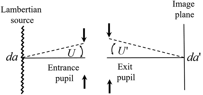
We will initially make the thin-lens simplification that both pupils lie at the lens and have the same diameter . Real compound lenses can have different entrance and exit pupils; the distinction becomes important at close focus.
From scene radiance to collected power
Radiance , measured in , describes power traveling in a specified direction per projected source area and per solid angle. Irradiance , measured in , describes power arriving per image-plane area. They are not interchangeable: a lens must select a cone of directions from the source and map the resulting power onto an image area.
Consider a small, on-axis source patch of area , perpendicular to the optical axis, at distance . Assume its radiance is approximately constant across the directions admitted by the lens. For small angles, the entrance pupil area and the solid angle it subtends at the patch are
For a lossless lens, the power collected from that patch is approximately
The factors have distinct jobs. Increasing increases collected power quadratically; moving a fixed physical patch farther away reduces the pupil’s solid angle quadratically. No focal length appears yet because we have calculated power entering from that patch, not its concentration at the image.
The University of Arizona optics notes Section 11 Radiative Transfer derive this result and then divide by the image area. In the PDF, use the slides bearing printed numbers around 11-9 and 11-10, particularly “Radiative Transfer – The Optical System - Continued.” The extracted mathematical symbols can be difficult to read, so follow the equations as displayed on the slides.
Read the thin-lens power calculation and its transition to the camera equation. Track which area is in the object plane and which is in the image plane.
Begin at the paragraph setting up the pupil. Continue through the slide headed “Radiative Transfer – The Optical System - Continued,” stopping after the camera equation. In particular, locate the step that uses the squared magnification to obtain image area.
Why f-number governs image irradiance
Last lesson gave the magnitude of transverse magnification as , where is image distance. The image of our patch therefore occupies area
All the collected power is directed onto that area in the ideal model. Dividing by cancels both the patch area and the inverse-square dependence on object distance:
This is the on-axis camera equation in its paraxial, lossless form. The ratio describes the image-side cone at the actual focus setting. For a distant scene, , so
The proportionality explains conventional aperture stops: multiplying the f-number by halves the ideal irradiance. At fixed focal length, opening the entrance pupil to twice its diameter gives four times the irradiance.
There is an apparent puzzle here. At f/4, a lens has twice the entrance pupil diameter of a lens at f/4. For the same fixed scene patch at a distant object distance, it collects about four times as much power. But its image of that patch has about four times the area. The two images consequently have approximately the same irradiance, assuming equal transmission and negligible field effects. A larger pupil has not made radiance appear brighter merely by spreading its collected power differently.
The distance cancellation needs its conditions stated carefully. It concerns a resolved patch of unchanged radiance, with the camera focused on it. It does not say that a fixed patch sends unchanged total power to the lens as you move away; that power falls. Nor does it say irradiance is exactly independent of distance when close focusing changes . An unresolved point source, such as a star, is also a different measurement problem: the camera equation for a resolved, extended scene patch is not its brightness formula.
Close focus: the working f-number
For our thin lens, , so
Consequently, the relevant working f-number is
At magnification, : a nominal f/4 lens behaves as working f/8 in this symmetric thin-lens model, giving one-quarter the distant-focus irradiance for the same scene radiance. This is why the familiar rule must be qualified for close-up photography.
The f-stops here, by Marcus R. Hatch and David E. Stoltzmann, treats that qualification explicitly. In the subsection “Obeys Abbe,” find the discussion beginning with a copy lens and read through its finite-conjugate formula. The formula uses a positive magnification magnitude, as our does. Its later pupil-magnification correction explains why need not hold exactly for an asymmetric compound lens.
Read this technical treatment to identify the assumption behind the simple working-f-number formula, rather than treating a barrel f-number as a universal image-cone measurement.
In “Obeys Abbe,” start at the copy-lens example. Continue through equation 6 and stop at its stated limitation. The following equation 7 supplies the exit-to-entrance pupil size correction if you want to inspect how a real lens departs from the symmetric model.
Throughput: the area–solid-angle budget
The product of an accepted area and an accepted solid angle is geometric throughput, often written , with units . For our small source patch,
This definition separates properties of the scene () from the geometry of the selected ray bundle (). Throughput is not irradiance: throughput describes how much area-and-angle the optical system accepts, while irradiance describes how the accepted power is distributed across the image.
We can check the same throughput on the image side. The image area is . At that image patch, the exit pupil in our thin-lens model subtends . Hence
The lens trades area against angle without creating geometric throughput. In air, this is also the basis for conservation of radiance in an ideal lossless imaging system. In media of differing refractive index, the corresponding invariant requires the refractive-index factor; our result assumes air on both sides.
Return to Section 11 Radiative Transfer for the treatment headed “AΩProduct,” followed by “AΩProduct - Continued” and “Conservation of Radiance” (printed slide numbers around 11-15–11-19). Compare its object-side and image-side products with the cancellation above.
Read the area–solid-angle argument as a second way to understand the camera equation. Focus on what is conserved in a lossless system, rather than memorizing the slide notation.
Under “AΩProduct,” start at the assumptions and continue through “AΩProduct - Continued,” ending at basic throughput. Then, under “Conservation of Radiance,” read from the lossless case through the immediately following “Camera Equation - Revisited” slide. Follow the equation beneath its opening sentence to see how image-side solid angle yields irradiance.
As a numerical check, take , , and thus . Let a on-axis patch at have . Its entrance-pupil area is about , giving
The lens equation gives . Its image area is about , so . By comparison, the distant-focus approximation for the same radiance gives . The modest difference is the working-f-number effect at this focus distance.
Transmission is not aperture size
So far, every admitted ray reached the image. A real lens loses some light to reflection, absorption, scattering, or other components. If its on-axis power transmission is , then, within our model,
At distant focus, the T-number packages that loss into an equivalent ideal f-number:
For example, f/4 with has . Its geometrical entrance pupil has not shrunk; it transmits the same on-axis power that an ideal lossless lens of approximately f/4.44 would deliver under these assumptions. The product describes geometric throughput, while describes the transmitted power from radiance .
In The f-stops here, the subsection “Shapes other than circles” moves from entrance-pupil area to the T-number. Read the transmission discussion there, stopping before the subsequent table of common f-stops.
Read why an aperture ratio alone does not specify the delivered image irradiance of a lossy lens.
Within “Shapes other than circles,” begin at the transmission passage. Read equation 9 and its interpretation, ending at T-stop calibration.
These equations describe an on-axis, paraxial ray bundle. Away from the image center, projected areas, ray angles, and mechanical obstruction of the pupil can alter irradiance. A very fast or strongly asymmetric compound lens can also require more careful pupil geometry than and alone provide. Those qualifications do not change the central distinction: pupil area controls admitted power from a specified patch; image-side cone angle controls how much irradiance that power produces.
What to retain
For a circular entrance pupil, . For a resolved on-axis scene patch imaged by a lossless thin lens in air, its collected power is , and its geometric throughput is . Dividing that power by the magnified image area gives
with at distant focus. Transmission reduces the result further; the T-number expresses that reduction for comparing delivered irradiance.
A wider aperture admits more light, but it also changes which rays participate in forming each image point. Next lesson examines the resulting competition between diffraction and geometric defocus as the aperture changes.