Recommended resources
The freely available resources this lesson will direct you to.
Hello. This course follows the camera as an engineering system: first the optics that form an image, then the materials that record it, the mechanisms that control exposure and focus, and finally electronic sensors and computational imaging. We begin with the geometric model behind both the camera obscura and the photographic lens.
In this lesson, you will derive where an image forms, how large it is, and how much of a scene fits on the recording surface. The distinction to watch is simple but consequential: a pinhole projects onto a plane you choose; a lens focuses an object plane onto a plane determined by its focal length.
A pinhole: projection without focusing
Imagine an object in front of a tiny hole, with a recording surface behind it. In the ideal geometric model, only one ray from each object point passes through the hole. Where that ray meets the surface is the point’s image location.
The diagram below shows both the physical sensor, to the left of the camera center, and a virtual image plane, to its right. The latter is a convenient way to draw upright projection coordinates; it is not a second sensor.
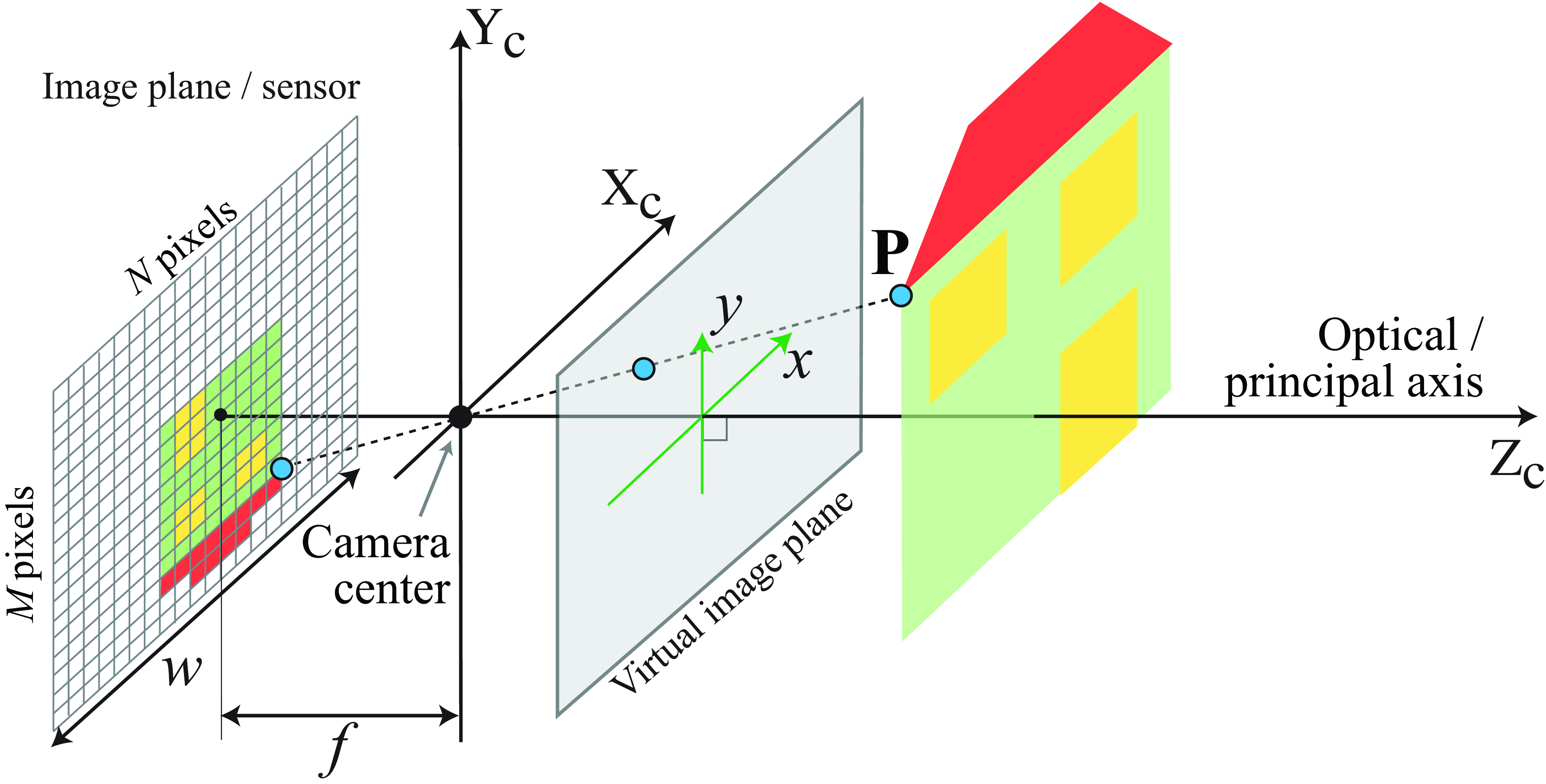
Set the hole at the origin and point the -axis toward the scene. An object point has coordinates , where . Put the physical sensor at , with . The ray through the origin has transverse coordinates proportional to its axial coordinate, so similar triangles give
The minus signs express inversion. If instead we draw a virtual plane at , its coordinates are and . Keeping these two planes distinct prevents a common sign error when moving between photographic diagrams and computer-vision projection equations.
Watch the following explanation for the ray geometry and for why projected scale depends on object depth. Its presentation uses a virtual image plane; translate its coordinates to the physical sensor using the minus signs above.
Pinhole and Perspective Projection | Image Formation
Watch “Pinhole and Perspective Projection | Image Formation” from First Principles of Computer Vision to see the similar triangles behind perspective projection.
Watch projection geometry, where the pinhole and image-plane coordinates are established and the projection equations are obtained. Then watch magnification, focusing on the assumption that the measured object segment lies at one depth.
Suppose a flat object of height lies perpendicular to the optical axis at depth . Apply the projection equation to its top and bottom: their separation on the physical sensor is , if upward object height and sensor height use the same coordinate direction. The signed transverse magnification is therefore
This is a scale for an object at a specified depth, not a single scale for an entire three-dimensional scene. Two equally tall objects at different depths have different image heights.
Notice what this derivation does not specify: a required sensor distance. In an ideal pinhole camera, you can move the sensor to another distance and still intercept one projected ray per object point. Image size changes, but there is no thin-lens focusing equation. A real hole has finite diameter, so “one ray” is an idealization; we will examine the resulting resolution trade-offs later in this module.
A thin lens: making many rays meet
A pinhole rejects nearly all the rays arriving from an object point. A lens offers a different solution: admit rays across an aperture and refract them so that they meet again at an image point. Its shape and refractive index determine its focal length . Here, paraxial means that ray heights and angles are small enough for the small-angle approximation to describe their paths; thin lens means that we neglect the separation between the lens’s refracting surfaces when tracing the rays.
The optical origin of this model is worth seeing before using it. In Section 6.2, “Lensmaker’s Formula,” of Foundations of Computer Vision, follow how small-angle Snell refraction connects surface curvature to focal length. You need not memorize the particular symmetric-lens curvature formula; the important result here is that, within this approximation, the lens supplies a definite focusing power.
6 Lenses – Foundations of Computer Vision
Read the treatment of paraxial refraction to connect the ray geometry below to the physical action of a lens.
In Section 6.2, begin at the paragraph opening “For small angles” and read the paraxial derivation through the displayed lens equation and focal-length definition immediately following “Lensmaker’s Formula.” Focus on why bending varies with ray height and how a single focal length summarizes that behavior; you can leave the later unequal-curvature generalization for another time.
Now put a converging thin lens at the origin. An upright object of height is at distance in front of it. If a real image forms, let its plane be at distance behind the lens, with signed image height . Trace two rays from the object’s top:
- The central ray passes through the ideal thin lens’s center without changing direction. Similar triangles give .
- A ray parallel to the optical axis reaches the lens at height , then passes through the rear focal point at distance . At the image plane, its height is .
Both rays must reach the same image point. Equating their heights and cancelling gives
Solving for the image distance, then returning to the central ray, yields
This derivation assumes , so that and a real image can be placed on a sensor. An object at sends the ideal outgoing rays parallel, giving no finite real-image distance; an object inside does not form a real image behind this lens.
There is also a compact way to read the equation in terms of ray slopes. For an axial object point, a ray reaching lens height has incoming paraxial slope , measured along its direction of travel. To reach the axial image point, its outgoing slope must be . The lens changes that slope by . Thus : the reciprocal-distance equation is a statement of how much convergence the lens must add.
Section 6.3, “Imaging with Lenses,” in Foundations of Computer Vision gives the corresponding central-ray and focal-ray rules. One caution: its numbered rule 4 states the magnification ratio as . With its definitions of as object distance and as image distance, the image-to-object height ratio instead has magnitude , as the central-ray triangles above show.
6 Lenses – Foundations of Computer Vision
Read the ray-tracing rules to consolidate the geometric derivation and the meaning of conjugate object and image points.
In Section 6.3, start with the opening discussion of the ray through the lens center. Read the ray rules through the four numbered properties. Use the central-ray diagram to check the magnification ratio rather than relying on the ratio printed in rule 4; stop before Section 6.3.1, “Depth of Field.”
The limiting cases make the equations easier to interpret. As becomes very large, becomes negligible and approaches : a lens focused on a distant scene places its sensor approximately one focal length behind the lens. At , the image also lies at and has the same size as the object, inverted. Moving the object closer to pushes the required image plane farther away and increases . A fixed sensor plane cannot therefore sharply image every object distance at once.
Field of view: which directions reach the frame?
Field of view is an angular extent, so it needs both a direction—horizontal, vertical, or diagonal—and a definition of the frame size. Let the sensor width be . For the ideal pinhole, a ray from a scene direction at half-angle to the optical axis meets the sensor edge at transverse distance . The right triangle at the hole gives
For the ideal thin lens focused at object distance , replace the pinhole-to-sensor distance by the image distance :
At distant focus, , giving the familiar photographic expression
Use sensor height in place of for vertical field of view, or the sensor diagonal for diagonal field of view. The arctangent follows from the right-triangle geometry; treating the lens as a thin, well-behaved imaging system is the approximation. A real wide-angle lens need not obey this ideal rectilinear model all the way to its frame edge.
The geometrical-optics notes Section 3 Imaging With A Thin Lens provide a useful diagrammatic check. Their “Field of View” slides distinguish half-angle from full angle and show why a rectangular detector has different horizontal, vertical, and diagonal fields.
Section 3 Imaging With A Thin Lens
Read the field-of-view slides in the geometrical-optics notes to connect sensor dimensions, image height, and angular coverage.
Go to the slides numbered 3-46 through 3-48, beginning with “Field of View” on slide 3-46. Read the field diagrams through the horizontal, vertical, and diagonal detector discussion on slide 3-48. Follow the drawn triangles and labels if the PDF’s text extraction obscures a formula. Stop before the numerical focal-length table on slide 3-49.
Consider a thin lens and a -wide sensor. Focused at infinity, its horizontal field of view is , approximately . If an object is from the lens, however, the image equation gives . The horizontal angular field for that focused object plane is then about , and a -tall object in that plane produces an inverted image about tall. Using in place of is excellent for distant scenes, but this example shows precisely where the approximation enters.
Equivalently, the object-plane width captured at distance is : magnification tells you how much object fits across the sensor, while field of view expresses the same geometry as an angle at the camera.
What to retain
A pinhole maps scene points by similar triangles; its sensor spacing sets image scale and angular coverage, but is not a focusing distance. A thin lens uses refraction to bring many rays from a point together. For a real image of an object beyond its focal length, its image distance and signed magnification are
Finally, for sensor width , the ideal horizontal field of view is , with at distant focus. These relationships are the geometric baseline for the rest of the optics module. Next, we will ask what they leave out: how much light the lens admits, and how aperture size determines image-plane irradiance and throughput.