Recommended resources
The freely available resources this lesson will direct you to.
Hello! In the previous lesson, you traced the conditions that allow a laptop to progress from standby power to firmware execution. A schematic shows where those conditions become electrical connections: which component has a particular pin, what else shares its signal, and which supply powers it.
This lesson is about reading a small excerpt accurately, not memorizing every symbol on a motherboard. You will distinguish component references from pin numbers and net names, follow a connection that disappears into a label, identify power rails, and interpret an active-low reset or button signal without confusing “high voltage” with “active.”
A schematic records connections, not physical placement
A schematic is an electrical map. A chip drawn beside a connector need not sit beside it on the board; pins arranged neatly along a symbol’s edge need not appear in that order on the physical package. What matters first is the identity of each component and the connectivity of its pins.
Watch DigiKey’s How to Read a Schematic for a quick visual foundation. Its examples distinguish pictorial drawings from schematics and show how pins, junctions, reference designators, and labels work together.
How to Read a Schematic - Another Teaching Moment | Digi-Key Electronics
DigiKey Electronics’ “How to Read a Schematic” introduces the graphical conventions you will use on the excerpt below.
Watch schematics versus pictures for the difference between electrical representation and physical appearance. Then watch pins and junctions, paying attention to why the arrangement of IC pins on paper is not a package drawing and how dots distinguish connected crossings. Finish with names and labels to see how a reference designator identifies a part while a net label identifies a connection.
The three kinds of text you will repeatedly encounter answer different questions:
- Reference designator: Which component?
U1identifies one integrated circuit;R4identifies one resistor. The prefix suggests the part type, while the number distinguishes it from others of that type. - Pin number and pin function: Which terminal on that component, and what is it for? A chip may have pin
20markedTXD. The number is needed to locate a physical terminal; the function name explains its intended role. - Net label: What electrical connection does this wire belong to? Wire segments carrying the same label are treated as connected, even when no line runs between them on the page.
SparkFun’s How to Read a Schematic develops those distinctions with examples. Read the specified subsections rather than the entire symbol catalogue.
SparkFun’s “How to Read a Schematic” explains component names, connected junctions, repeated net labels, and voltage-node symbols. Read it to establish the conventions before applying them to the provided excerpt.
In “Name Designators and Values,” find the subsection “Names and Values”; read component names, then glance at its prefix table. In “Reading Schematics” > “Nets, Nodes and Labels,” read from nets through labels; include the “Junctions and Nodes” and “Net Names” subsections and their pictures. Finally, in “Schematic Reading Tips” > “Recognize Voltage Nodes,” read voltage nodes. Focus on what establishes a connection, not on where objects happen to be drawn.
One especially important rule is that a dot at a wire junction denotes a connection. Lines crossing without a junction dot generally do not connect. A label is different: it can establish a connection without a continuous visible line. On a full motherboard drawing, that is what lets a signal appear on an EC sheet and again on a power-control sheet without a wire snaking across both pages. Consult that drawing’s legend if its junction or label convention is unclear.
Read the provided excerpt one connection at a time
The following annotated schematic is a small USB-to-serial circuit, not a laptop motherboard. That makes it a manageable place to learn the notation. The colored diagonal arrows highlight corresponding labels for the tutorial; they are annotations, not conductors. Follow the thin schematic wires and their labels instead.
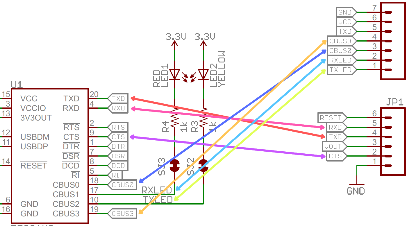
Start at the left-hand rectangle. U1 identifies the IC. The small 20 beside its TXD pin is a pin number, not a voltage or a second component. A short wire from that pin ends in a tag labeled TXD. On the right, connector JP1 has a terminal labeled TXD at pin 4. The repeated net label tells you that these points share the TXD connection, despite the gap on the page. The upper connector also shows a TXD-labeled terminal. A matching name establishes connectivity; it does not, by itself, establish which device is transmitting at a particular moment.
The same approach works for RXD: locate U1 pin 4, read the label on its wire, then find the matching label at JP1 pin 5. Notice how easily pin 4 and connector pin 4 could be confused if you looked only at numbers: they belong to different components. Always state a point as component, pin number, and net when precision matters—for example, “U1 pin 20, TXD net.”
Other marks play different roles. R4 identifies a resistor, and 1k gives its resistance value; neither is a net name. JP1 identifies a connector, whose numbered contacts provide places where the named nets leave this circuit. The arrows marked 3.3V designate a named supply connection to the LED circuitry, while GND marks the ground net. Those symbols avoid drawing a wire back to every point at which the supply or ground is used.
A named supply is not evidence that the supply is currently present or healthy. Likewise, VCC on a chip pin or connector is a name or function, not a license to assume its voltage equals the separately marked 3.3V rail. You would need the full schematic and component documentation to establish how those supplies relate. That distinction will matter when you later inspect laptop rails: a drawn +3V rail describes a designed connection; whether the board produces it is a separate observation.
Read active-low names as statements about assertion
The earlier power-sequencing lesson used names such as RSMRST#. The # indicates active low: when the signal is at its defined low logic level, the reset is asserted; when it is at its defined high level, the reset is released. Schematics may instead use /RESET, RESET_N, RESET_L, or an overbar. These are naming conventions, so confirm an unfamiliar board’s convention and the receiving device’s pin definition.
Louis Rossmann’s short explanation uses a laptop power-management signal to show why “high” and “active” are not synonyms.
Electronics schematic reading; what does the _L mean as the suffix of a signal
Louis Rossmann’s “Electronics schematic reading; what does the _L mean as the suffix of a signal” concentrates on the active-low naming convention.
Watch the low suffix for the interpretation of PM_BAT_LOW_L: a low level asserts the named indication, while a high level leaves it inactive. Then watch button and reset for two further names. Treat the voltages and behavior shown as examples from that circuit, not universal values for every laptop.
An active-low name describes the meaning of a logic level, not necessarily the reason that level occurred. If a reset net reads low, the connected logic may be held in reset; the name alone cannot tell you which prerequisite failed. A low reading on an unpowered circuit also cannot automatically be interpreted as a valid asserted signal. You need its power domain, circuit, and measurement conditions.
Notice a limit in the provided image: it shows a pin and label called RESET, but the visible word RESET has no explicit active-low suffix or mark. Do not assign its polarity solely from that name. Consult the IC documentation or a fuller schematic. In contrast, RSMRST# from the previous lesson carries an explicit polarity convention.
Transfer the method to a laptop motherboard
Consider this illustrative, simplified fragment for an EC button input:
+3V_ALW
   |
 R17 (10k)
   |
   +---- EC_PWRBTN# ---- U5 pin 12 (EC input)
   |
 SW2 (normally open)
   |
  GND
Here R17 is a resistor connected to the named supply +3V_ALW; SW2 is a normally open switch connected to ground; and U5 pin 12 receives the EC_PWRBTN# net. With the rail operating and the switch open, the resistor tends to hold that input high. Closing the switch connects the net to ground, making the active-low button indication asserted. This example shows why tracing the circuit around a signal is more informative than reading its name alone.
It also reconnects the schematic to the startup sequence. Before interpreting an EC button indication, you would identify the EC’s supply and ground, the button net, and any conditioning components. Before interpreting a reset, you would identify the component that produces it, the components that receive it, and the relevant power domain. This is interpretation of the drawing, not yet a diagnosis from symptoms or a reason to short, inject, or force any signal.
A reliable reading order for an unfamiliar excerpt is to locate the component reference and pin, follow the wire through junctions and repeated labels, identify associated supply and ground nets, and only then interpret the signal’s name and polarity. Record what the drawing establishes separately from what would require a datasheet or a measurement.
Key takeaways
A component reference identifies a part; a pin number identifies one of its terminals; a net label identifies an electrical connection. Junction dots and repeated labels determine connectivity, while rail and ground symbols name shared supply connections—not their measured condition. For an explicitly active-low signal, low means asserted, subject to the circuit being powered and the signal being interpreted under valid conditions.
You can now turn a schematic fragment into a careful account of what is connected and what remains unknown. The next lesson uses observable startup symptoms to locate the likely stage of failure; this ability to separate schematic facts from assumptions will keep that classification evidence-based.