Recommended resources
The freely available resources this lesson will direct you to.
- Laptop Motherboard power sequence in detail with animation. Dhaka Lab and Institute.www.youtube.com
- Master Laptop Timing Diagrams in 20 Minutes | S5 to S0 Power States Explainedwww.youtube.com
- Power Sequencing — Basic Open Embedded Controller Firmware 4.01.00 documentationintel.github.io
- CrOS EC (Embedded Controller) - Configure AP Power Sequencingchromium.googlesource.com
Hello! Last lesson gave you a map of the CPU, PCH, EC, and firmware flash. Now we will add time to that map: what must become powered, what must be released from reset, and which “power good” indications must arrive before the CPU can begin executing platform firmware.
The aim is to trace a representative laptop startup, not memorize one board’s voltages or signal names. Those details vary. The transferable skill is to distinguish a power rail from a signal that enables a rail, a signal that confirms it is stable, and a reset that prevents a component from running.
Begin before the power button
G3, mechanical off, means the main system has no operating power source. A small independent clock battery may still power a clock circuit, but the EC cannot be assumed to be running. In S5, soft off, the computer is shut down but a source is available and some standby circuitry can remain active. Pressing a button is useful only once circuitry capable of detecting that press has power.
On a representative laptop, connecting an adapter or usable battery allows input-power circuitry to establish the necessary standby supply. The EC can then run its own firmware and monitor the button. Depending on the design, other small power domains may also be active. “Always-on” means available under the board’s specified conditions, not necessarily present in every battery or disconnected state.
The state-machine image below provides orientation. It describes states and permitted transitions in one reference EC implementation; it is not a timing chart or a universal requirement to dwell in every intervening sleep state during startup.
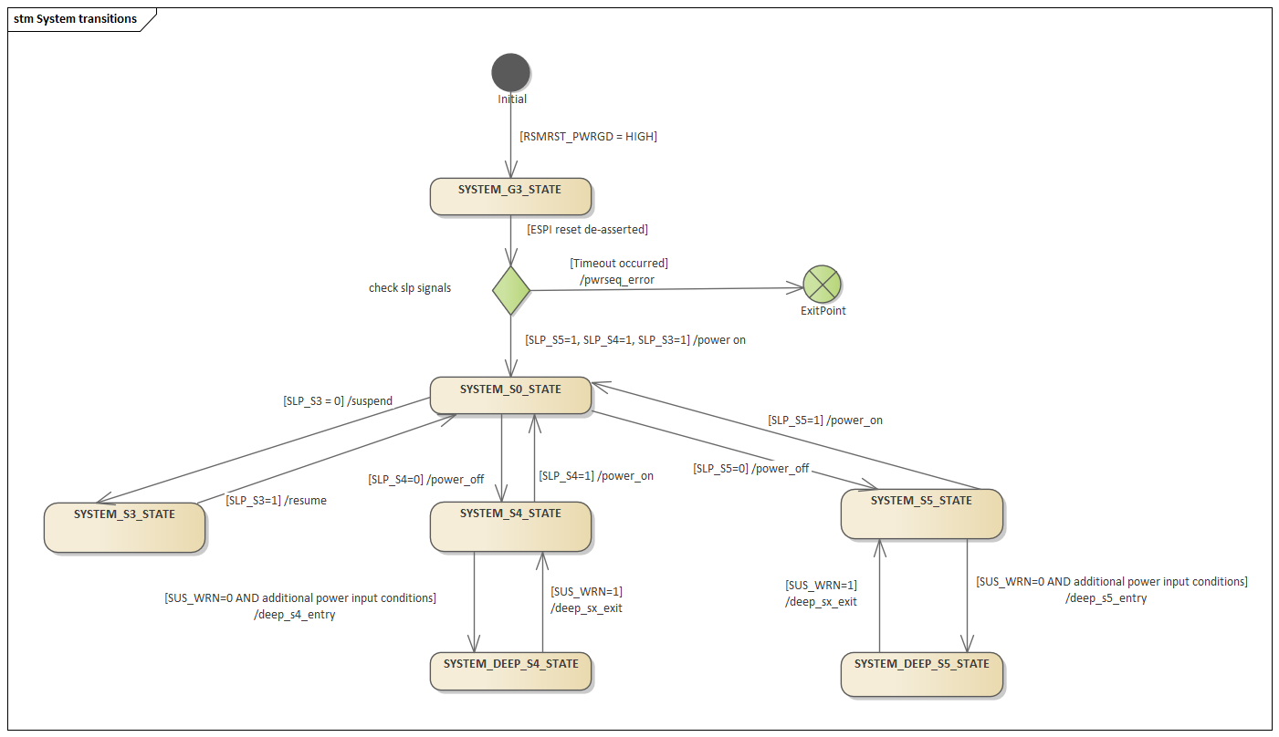
Our destination is S0, the system-on state. Reaching a state labeled S0, however, does not by itself prove that the CPU has successfully fetched firmware instructions. We will make that final boundary explicit.
Learn to read the signals as permissions and confirmations
The Intel EC firmware reference names the signals in a particular PCH-and-EC design. Read its descriptions before following the sequence; pay particular attention to who receives each signal and what condition it reports.
Power Sequencing — Basic Open Embedded Controller Firmware 4.01.00 documentation
Read Intel's Power Sequencing reference to establish the roles of the button, resume-reset power good, all-system power good, and sleep signals.
In “Power Signals,” read the subsections “Power button input,” “RSMRST#_PWRGD,” “ALL_SYS_PWRGD,” and “SLP_Sx#.” Start at the signal descriptions and continue through the note below “SLP_Sx#.” Notice that some signals may travel as eSPI virtual wires rather than dedicated physical pins.
The following picture puts those descriptions onto the block map from last lesson. Board logic is on the right, the EC in the middle, and the PCH on the left. The numbered ovals refer to actions in this reference sequence; they are not connector pin numbers or logic levels.
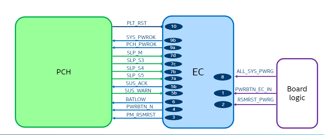
Several distinctions make the diagram much easier to trace:
- A power rail supplies electrical power to a component. Its presence alone does not say that its voltage is stable enough for operation.
- An enable tells a regulator or switch to supply a rail. An enable being active does not prove the rail appeared.
- A power-good signal reports that a monitored supply or set of supplies satisfies its required conditions. In this reference design,
RSMRST#_PWRGDis an earlier prerequisite used for resume reset, whereasALL_SYS_PWRGDis checked later before the EC issuesPCH_PWROK. - A reset holds logic in a defined inactive condition until its prerequisites are met. For a name ending in
#—such asRSMRST#—low means asserted and high means released. A board may write an active-low suffix as_Nor_Linstead. Check the actual board documentation rather than inferring polarity from a loosely shortened label.
The EC’s button output is another useful example. The physical button input arrives at the EC; the EC sends a conditioned button indication to the PCH. In this diagram that PCH-facing line is PWRBTN_N, so a low level represents the asserted button signal. The button does not directly apply power to the CPU.
Trace the representative power-up
Now read the reference implementation’s “Flow for G3 to S0.” Its numbered actions are a guide to dependencies, not a promise that every laptop has precisely the same intermediate states, timing, or optional handshake.
Power Sequencing — Basic Open Embedded Controller Firmware 4.01.00 documentation
Read Intel's reference flow to connect the signals to startup events. Keep the EC, PCH, and board-power circuitry as separate actors while reading.
Under “System transitions,” find “ACPI System Transitions,” then “Flow for G3 to S0.” Read the state context and numbered flow, ending at action 10. Focus on the two checks before the EC reports power readiness: the earlier RSMRST_PWRGD input and the later ALL_SYS_PWRGD input.
We can group the flow into four meaningful phases.
1. Establish standby operation and release resume reset. After a valid source is available, the EC needs its own supply, reset release, clock, and functioning firmware to participate. The reference EC checks the board’s RSMRST#_PWRGD input. Once the required early power conditions hold, it can release its RSMRST# output to the PCH. Releasing resume reset is not the same thing as completing system power-up: many CPU and memory supplies may still be absent.
2. Convey the request to start. The EC detects a valid button press and conveys it to the PCH. It also participates in any required power-source or battery-low indication. Some designs use an additional deep-sleep exit exchange, shown as SUS_WRN and SUS_ACK in the reference. Treat that exchange as conditional, not as a mandatory feature of every laptop.
3. Bring up the system power domains. The PCH’s SLP_S5#, SLP_S4#, and SLP_S3# indications tell the EC and board logic about the host’s sleep-state transitions. In this naming convention, an asserted, low sleep signal indicates the corresponding sleep condition; deassertion is part of proceeding toward the fully on state. Board logic uses the appropriate indications to enable additional regulators. These can include memory and processor-related supplies, but their order, names, and voltages require a board-specific design guide or schematic.
Crucially, a sleep signal changing is a request or state indication, not proof that the enabled rail became healthy. The reference EC waits for ALL_SYS_PWRGD from board circuitry, indicating that the monitored SoC supplies have stabilized. It then issues PCH_PWROK and, if the platform requires it, SYS_PWROK. Two power-good names exist because they serve specified recipients and conditions; they are not interchangeable labels for “the laptop has power.”
4. Observe reset release. The reference flow ends by waiting for the PCH’s platform-reset indication, PLT_RST. A reset held asserted prevents the affected logic from proceeding even when its rails are present. Conversely, observing platform reset released is strong evidence that startup has passed several earlier gates—but it does not certify every component on the motherboard. The CPU has its own platform-specific power and reset prerequisites; do not assume that the EC-facing PLT_RST line is literally the CPU’s reset pin.
A compact way to remember the trace is to ask three different questions at each checkpoint: Is there power? Has that power been confirmed good? Has the relevant reset been released? Answering only the first question leaves much of the sequence unexplained.
Where power sequencing meets firmware execution
Last lesson placed platform firmware in SPI flash, typically accessed through platform I/O logic in the representative two-chip design. Once the CPU’s supplies, power-good requirements, clocking, and reset conditions are satisfied, it begins execution at its reset vector. The platform maps the initial firmware code so that the CPU can fetch instructions; access to the SPI flash and its supply must work for that path to succeed. Later firmware initialization and operating-system boot are separate steps.
This gives a precise endpoint for this lesson:
A powered board is not yet a CPU executing firmware. The relevant supplies must be stable, the platform must permit startup, and the CPU must leave reset and successfully fetch its first firmware instructions.
For example, suppose the EC detects the button and RSMRST# is released, but ALL_SYS_PWRGD never asserts. The trace has passed the early standby and button checkpoints but has not established that all monitored system rails are good. It would be premature to call this a firmware-flash fault. Equally, if platform power-good and reset indications appear normal but there is no image on the screen, that absence alone cannot tell you whether the CPU fetched firmware: display initialization happens later. These observations locate a boundary for investigation; they do not prove which individual chip is defective.
Use this sequence as a reading framework for documentation and observations, not as an invitation to bridge signals or force regulators on. The exact voltage, polarity, timing, and measurement point must come from the particular board’s documentation.
Key takeaways
From mechanical off, a usable source first makes standby control possible. The EC can then validate and relay the power-button request, coordinate with the PCH’s sleep indications, and wait for board power-good evidence. Power-good indications permit the appropriate resets to be released. Firmware execution begins only when the CPU’s own prerequisites are met and it can fetch its initial instructions.
In the next lesson, you will apply this trace to a basic motherboard schematic, identifying the component references, rails, net labels, and active-low notation that turn these functional signals into connections on a particular board.