Recommended resources
The freely available resources this lesson will direct you to.
Introduction
In our previous lesson, we established the fundamental principles governing rocket motion by exploring Newton's three laws. You learned that an unbalanced force is required to change a rocket's state of motion (First Law), how thrust is generated as an action-reaction pair (Third Law), and how the rocket's acceleration relates to force and its changing mass (Second Law).
This lesson builds directly on that foundation. We will now focus on a critical engineering skill: visualizing these forces. You will learn to draw a free-body diagram, a simple yet powerful tool used to represent all the forces acting on a rocket. Mastering this will allow you to translate a complex physical scenario into a clear, analyzable format. By the end of this lesson, you will be able to construct a complete free-body diagram for a rocket during its launch phase, correctly identifying and representing the forces of thrust, weight, and drag.
1. The Free-Body Diagram: A Tool for Analysis
Before applying this to a rocket, let's define what a free-body diagram is and establish a systematic process for creating one. A free-body diagram is a simplified sketch that isolates an object from its surroundings and shows all the external forces acting on it as vectors (arrows). The purpose is to deconstruct a problem into its essential components so that you can apply Newton's laws.
The following video provides a concise overview of the five essential steps for drawing any free-body diagram. Pay close attention to the method, as we will be applying it directly to our rocket problem.
Closer Look: Free Body Diagrams | Physics in Motion
Watch the beginning of the video "Closer Look: Free Body Diagrams" from GPB Education to learn the formal steps.
Please watch the section that outlines the five steps for drawing a free body diagram. This provides the structured procedure we will follow.
The five steps can be summarized as:
- Draw the object's outline.
- Place a dot at the center of mass.
- Draw vectors (arrows) from the dot for each force.
- Ensure vector length represents the relative magnitude of the force.
- Label each vector clearly.
This structured approach is fundamental in engineering as it ensures no forces are missed and their relationships are correctly visualized.
2. Identifying Forces on a Rocket at Launch
For a rocket ascending vertically immediately after launch, we are primarily concerned with three major forces. You've been introduced to them, but let's formally define them in this context.
- Thrust (T): The propulsive force generated by the engine, acting upwards along the rocket's main axis.
- Weight (W): The force of gravity pulling the rocket down towards the Earth's center. It is calculated as , where is the rocket's mass and is the gravitational acceleration.
- Drag (D): The aerodynamic resistance from the atmosphere that opposes the rocket's motion. As the rocket moves upward, drag acts downward.
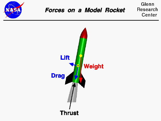
A fourth force, lift, is generated by airflow over the fins. For a perfectly vertical launch with no wind, its effect on vertical motion is negligible. Its primary role is to provide stability by correcting any deviations from a straight path, a topic we will cover in detail in a later module on flight stability. For now, our diagram will focus on the three primary forces governing vertical motion.
The following image from NASA illustrates these four forces on a model rocket. Notice the direction of each vector.
3. Constructing the Rocket's Free-Body Diagram
Now, let's combine the formal method with the specific forces acting on a rocket. We'll walk through the construction of the free-body diagram for a rocket that is actively accelerating upwards off the launch pad.
The video below provides an excellent step-by-step walkthrough of this exact process. The instructor first identifies the forces and then, critically, discusses why their relative magnitudes—represented by the length of the arrows—are so important.
Watch this segment from "Rocket Launch" by Physics with Professor Matt Anderson. It demonstrates the thinking process behind creating the free-body diagram.
First, watch the section where the forces are identified and drawn: identifying forces. Next, and most importantly, watch the following section where the diagram is corrected based on the rocket's acceleration. This highlights the significance of vector length: correcting the diagram.
As the video makes clear, for a rocket to accelerate upwards, the upward force must be greater than the sum of the downward forces. This means:
Your free-body diagram must reflect this reality. The vector for Thrust must be visibly longer than the vectors for Weight and Drag combined. This visual rule is the direct application of Newton's second law (). A net upward force is required for upward acceleration.
The image below provides a perfect illustration of this principle. It shows the free-body diagram "During launch" where the rocket is accelerating, and contrasts it with the diagram "After thrust has finished," where the rocket is coasting and decelerating.

Focus on the left-hand diagram, "During launch." It correctly shows a large thrust vector and smaller drag and weight vectors, leading to a "Resultant force" pointing upwards. This is the net force that causes acceleration.
To solidify this, the following reading explains the interplay of these forces in text form.
[PDF] Forces on a Model Rocket
This document from rockets4schools.org provides a clear, textual explanation of the forces at liftoff, reinforcing what you've just seen in the videos.
Please read the section that describes the forces at liftoff, starting from this passage. It explicitly states that thrust must be greater than weight plus drag for the rocket to continue accelerating.
Conclusion
In this lesson, you have learned how to create a free-body diagram for a rocket during launch, a fundamental skill for any aspiring rocket builder. This tool allows us to move from abstract laws of motion to a concrete, quantitative analysis of flight.
Key Takeaways:
- A free-body diagram is a visual representation that isolates an object and shows all external forces acting upon it as vectors.
- For a rocket accelerating vertically at launch, the three primary forces are upward Thrust (T), and downward Weight (W) and Drag (D).
- To represent upward acceleration correctly, the thrust vector's length must be greater than the sum of the lengths of the weight and drag vectors. This signifies a positive net force in the upward direction.
You are now able to take a physical situation—a rocket launching—and translate it into a structured diagram. In our next lesson, we will put this diagram to work. We will use it to write the mathematical equation for the net force and then calculate the rocket's acceleration, taking the first step towards simulating and predicting a rocket's trajectory.