Recommended resources
The freely available resources this lesson will direct you to.
Welcome back. In the previous lesson, you marked the point of interconnection (POI), point of common coupling (PCC), study area, and ownership boundary on a one-line diagram. Those labels now give you places to attach requirements. A voltage criterion at Bus B, for example, is not the same requirement as a reactive-power capability criterion at the high side of the plant transformer.
This lesson turns the hypothetical 100 MW solar plant into a requirements-to-study traceability matrix. You will build a table that connects each requirement to its source, the study that will assess it, the location and criterion used for assessment, and the evidence a reviewer should expect. Allow about 40 minutes, including the short video and readings.
What the matrix must let a reviewer trace
A requirements traceability matrix is more than a list of studies. It lets a reviewer start with a requirement and find its planned assessment—and start with a study result and find the requirement that justified doing the work. That second direction matters: a result may be technically interesting without answering an agreed project question.
Watch Mike Clayton’s explanation for the basic structure. His examples come largely from project management and software; here, a power-system study case and its recorded results take the place of a test case.
What is a Requirements Traceability Matrix? And How to Create One.
“What is a Requirements Traceability Matrix? And How to Create One,” from Online PM Courses - Mike Clayton, introduces the purpose and minimum contents of a traceability matrix.
Watch the purpose and the contents for the links among needs, deliverables, and tests. Then watch two-way traceability. As you watch, substitute “study result” for “test result” and consider how you would find the source of an unexplained study case.
The example matrix below shows a useful layout: each requirement has an identifier, source-related information, acceptance criteria, and test cases. For an interconnection study, those fields need more electrical precision. “Voltage acceptable” is not enough; the row must say which bus, which operating conditions, which measurement, and which approved limit.
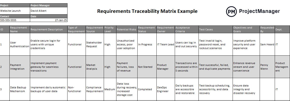
A practical row answers five questions: What is required? Who or what requires it? How will it be assessed? What constitutes an acceptable result? Where will the evidence be recorded? If one of those answers is unknown, the row remains open rather than silently acquiring an assumed answer.
Separate requirements from guidance and study methods
Before filling the table, classify your sources. A signed project agreement, applicable tariff provision, or confirmed utility criterion might supply a governing requirement. A study brief can define a project-specific assessment. A guideline may suggest a sensible performance question without imposing that question on this particular plant. A study-process manual may tell you what analyses and data are expected without supplying every numerical pass limit.
Read these two short portions of PJM Manual 14G as an example of how a study process describes its analyses, not as proof that PJM governs our hypothetical plant. Its jurisdiction has not been specified.
PJM’s manual distinguishes the analyses supported by feasibility-study data from those supported by system-impact-study data. Use it to see why a matrix needs a study-method column.
In Attachment A, Section A.2, “Data Requirements for PJM RTEPP Feasibility Studies” (p. 46), read the feasibility scope, ending with its stated analyses. Then find Attachment B, Section B.2, “Data Requirements for PJM RTEPP System Impact Studies” (pp. 57–58), and read the impact scope. Focus on the additional analysis named for the impact-study phase; do not infer a voltage or fault-duty limit from this passage.
For inverter-based generation, NERC’s Improvements to Interconnection Requirements for BPS-Connected Inverter-Based Resources offers examples of performance topics and the models used to examine them. Its Table 1.1 consists of recommended improvements for transmission owners developing requirements. A recommendation belongs in a matrix as candidate guidance until the applicable project documents establish whether and how it applies.
NERC’s guideline provides candidate performance requirements in Table 1.1 and corresponding modeling considerations in Table 1.2. Read these portions to practice linking a performance question to a suitable study representation, while preserving the distinction between guidance and a confirmed project obligation.
In Chapter 1, Table 1.1, read the “Capability Curve” entry and its point-of-measurement note on p. 2, from composite capability. On p. 4, read the “Fault Ride-Through Capability” entry from ride-through guidance. Notice the difference between a qualitative expectation for credible events and a quantitative performance envelope. Then, in Chapter 1, Table 1.2 (pp. 8–9), read from the “Steady-State Modeling” entry through the “Electromagnetic Transient Modeling” entry: modeling options. Focus on what each model is intended to represent. Do not treat every listed model as automatically required for every project.
One subtlety from the reading is particularly important for our table: NERC discusses a composite active- and reactive-power capability curve at a point of measurement (POM). The POM must be identified from the applicable requirement; it is not automatically the POI, PCC, or inverter terminal. For the worked example, we will provisionally place it on the high-voltage side of the plant step-up transformer and flag that placement for confirmation.
Build the solar-plant matrix
Keep the electrical picture from the previous lesson: the solar plant connects through its transformer and tie line to Bus B, which the example documents identify as the POI. Bus B is also the PCC for the stated shared-system question. Ownership changes at Terminal T on the project branch. None of those facts makes Terminal T an appropriate voltage-measurement location.
Start each matrix row with one assessable claim, not a broad topic such as “voltage compliance.” Give it a stable ID. Next record the source and its status. Only then choose the study and cases that can produce evidence for that claim. Finally specify the measurement location, acceptance criterion, evidence file or report section, and person responsible for resolving gaps.
Here is a first-pass matrix. Every limit attributed to the illustrative project study brief is a made-up scoping placeholder, not a PJM, NERC, or universally applicable limit. “TBD” means the criterion or datum must be confirmed before a compliance finding can be made.
| ID and source | Assessable requirement | Study and essential cases or inputs | Measurement and acceptance criterion | Evidence, lead, status |
|---|---|---|---|---|
| R-01 — Illustrative project study brief; criterion unapproved | Assess the plant’s effect on steady-state voltage. | Power flow at high solar output and light load, for the agreed intact-system and single-outage cases. Needs network model, plant controls, and case definitions. | Bus B: voltage between 0.95 and 1.05 per unit in the specified cases, if this illustrative limit is approved. | PF-01: case-by-case voltage table; power-flow lead; criterion pending. |
| R-02 — NERC Table 1.1 capability-curve guidance; applicability unconfirmed | Demonstrate the plant’s composite active- and reactive-power capability. | Power-flow capability checks over specified active-power and voltage points. Needs manufacturer capability data, collector representation, and plant-control limits. | POM: results must cover an approved capability envelope at stated operating points; envelope and exact POM TBD. | PF-02: capability plot and model inputs; plant-model lead; source and criterion pending. |
| R-03 — NERC Table 1.1 fault ride-through guidance; applicability unconfirmed | Assess whether the plant stays connected and responds as required during agreed credible faults. | Positive-sequence dynamic study of an agreed fault and clearing set. Needs plant dynamic model, protection settings, and network cases. Escalate the method if the question cannot be represented adequately. | Record POI voltage, plant power, and connection status. No trip for agreed events except documented exceptions is a candidate qualitative test; quantitative envelope and exceptions TBD. | DY-03: traces and event-by-event disposition; dynamics lead; scope and criterion pending. |
| R-04 — Illustrative project study brief; rating data pending | Assess whether the Bus B breaker remains within its fault-interrupting duty. | Short-circuit study for specified fault types and source conditions. Needs network and transformer sequence data, applicable inverter fault-response data, and breaker ratings. | Bus B breaker: calculated duty must not exceed the applicable rating under the approved duty-assessment basis; rating and basis TBD. | SC-04: fault-duty comparison; protection lead; inputs pending. |
The matrix links requirements to studies, but it does not claim that an unsolved case has passed. For example, R-03 cannot be closed merely because a dynamic model runs: the agreed disturbance set, exceptions, measurements, and performance envelope still have to be established. Likewise, R-02 cannot be assessed at inverter terminals and reported as POM capability without accounting for the electrical path between those points.
Notice also that the method and the criterion are different fields. PJM Manual 14G illustrates why power flow, short-circuit, and dynamic analyses can appear in an interconnection process. It does not, in the passages read, approve our invented Bus B voltage band or provide this breaker’s rating. The matrix makes that gap visible.
Check coverage in both directions—and keep the matrix current
A useful quality check is to read the table twice. Forward, take each applicable requirement and find its case, measurement, criterion, and expected evidence. A row with only a study name is incomplete. Backward, take each proposed study case or report figure and identify the requirement or agreed engineering question it answers. A case with no justification may be worthwhile, but its purpose should be added to the scope rather than left unexplained.
One requirement can need several cases. R-03, for instance, may require different fault locations or clearing times; record those in a linked case register under the same requirement ID rather than duplicating an ambiguous “ride-through” requirement. Conversely, one solved power-flow case may provide evidence for both voltage and capability questions, provided the distinct measurement locations and criteria are evaluated separately.
Treat the matrix as a controlled working document. When a transformer, inverter model, control setting, grid case, or governing document changes, identify the affected IDs and evidence, note the revision, and decide which assessments must be repeated. The NERC guideline’s discussion of updating study models as project information improves is a useful reason for this discipline. A change in model data should not leave an earlier result appearing current without review.
The same construction works beyond solar. For a BESS, the rows would distinguish charging and discharging cases and might add an agreed state-of-charge condition to a performance test. For a data-center load, a row might trace a specified load-pickup profile to a voltage-impact study at the applicable grid interface. In either case, first establish the project’s actual requirements and measurement points; do not transfer the solar example’s limits by analogy.
Key takeaways
A defensible traceability matrix connects a specific, sourced requirement to an appropriate study, defined cases and inputs, an electrical measurement point, an acceptance criterion, and reviewable evidence. It also exposes what is not yet known. Guidance is not automatically a binding requirement, a study method is not a pass limit, and a completed simulation is not automatically a compliant result.
The next lesson will turn the missing inputs exposed by these rows into a model and equipment data-request checklist.