Recommended resources
The freely available resources this lesson will direct you to.
Welcome back. In the previous lesson, you linked four questions about a hypothetical 100 MW solar plant to power-flow, capability, dynamic, and short-circuit studies. Each matrix row named inputs it would need. This lesson turns those gaps into a data request that someone can act on: what to ask for, who is likely to hold it, which study needs it, and how to tell whether the response is usable.
Keep the same example: Bus B is the stated point of interconnection (POI), Terminal T marks the project ownership boundary, and the reactive-capability point of measurement remains provisional. Allow about 40–45 minutes, including the focused readings. The checklist is a scoping tool, not a claim that any one operator’s submission rules govern this hypothetical project.
Ask for an electrical description, not just a drawing
A data request starts with the boundary you intend to model. The illustration below shows why a label such as “connected at the substation” is insufficient. It depicts a large load, its own switchyard, customer interconnection facilities, a transmission-provider substation, another customer, and a wider grid that includes a wind farm. It is a useful boundary sketch, but it does not supply the bus voltages, impedances, ratings, or operating settings needed to construct a study model.
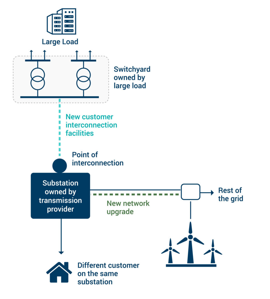
For the solar example, request a dated electrical one-line that identifies Bus B, Terminal T, the plant transformer, collector system, inverters, breakers, and any reactive-support equipment. Ask its preparer to mark the proposed voltage-control and reactive-capability measurement points. Those points should not be inferred from the ownership boundary. If the one-line says there are two transformers while the model contains one with no documented equivalent, that discrepancy needs resolution before the study proceeds.
The Modeling Guideline for NYISO Interconnection Data gives a concrete example of the information an operator can expect in a modeling package. Read it as a worked example of request specificity, not as the governing rule for our unspecified jurisdiction.
[PDF] Modeling Guidelines for NYISO Interconnection Data
Read NYISO’s “4. Necessary Data” to see how a one-line, electrical details, and distinct model files form a package rather than interchangeable substitutes.
In Section 4, “Necessary Data” (pp. 9–11), begin at the paragraph opening “For a complete modeling data package.” Read the package list through item 4’s dynamic-model exception. Focus on what the one-line must identify, then note the separate steady-state, short-circuit, and dynamic deliverables. Treat the named software versions and file types as NYISO-specific examples to confirm against current project instructions.
A useful distinction emerges here: equipment data describes the physical facility; a model file encodes a chosen representation of it. Request both. An electrical one-line may establish that a transformer exists, but it does not by itself provide a verified impedance. Conversely, a model value without a nameplate, test report, design calculation, or documented assumption may be difficult to check.
Turn each study input into a precise request
Start with the operating point. “100 MW solar plant” could mean inverter nameplate capacity, gross plant output, or net injection at Bus B. For R-01 and R-02, ask for the requested net MW at the POI, installed inverter MW and MVA, expected auxiliary demand and losses, and active- and reactive-power capability over the operating range. Request the intended control mode, controlled bus, voltage or power-factor setpoint if applicable, and operating limits. This prevents an apparently reasonable model from delivering the wrong quantity at the wrong location.
Then describe the electrical path between inverter and grid. Transformer winding voltages, connections, grounding, impedances, ratings, and taps affect voltage, reactive-power capability, and faults in different ways. Collector feeders and the tie line need lengths or equivalent parameters, resistance, reactance, charging where relevant, and ratings. Every impedance request should ask for its unit and base—for example, ohms or per unit on a stated MVA and voltage base. A bare value such as “” is not model-ready.
Read the targeted NYISO passages for the level of detail behind those requests. You do not need to adopt its bus-number conventions for the hypothetical plant.
[PDF] Modeling Guidelines for NYISO Interconnection Data
Use NYISO’s equipment subsections to distinguish operating quantities, transformer parameters, and branch data that a power-flow model needs.
In Section 5, “Steady State Modeling Requirements,” read Section 5.3, “Generator Data” (pp. 15–17), from the discussion of the controlled bus through generator capability and base data. In Section 5.4, “Transformer Data” (pp. 18–19), read from the GSU and PSU impedance-base discussion through ratings and tap data. Finally, in Section 5.7, “Line Data” (p. 22), read collector and line data. While reading, ask which values would come from equipment suppliers, which from plant design, and which are modeling choices.
The grid side needs its own request. The transmission provider or study coordinator may supply approved base cases, the assumed system topology, operating cases, and contingencies. The plant owner cannot establish those conditions merely by providing a plant model. If access or confidentiality conditions apply, record the authorized source and delivery route rather than substituting an unapproved grid equivalent.
Request different evidence for faults and dynamics
R-04 asks about breaker duty at Bus B. That requires more than an inverter MVA rating. The short-circuit analyst needs applicable network and transformer sequence data, grounding, and a representation of inverter fault-current behavior appropriate to the study method. The protection or equipment contact must also supply the breaker’s applicable interrupting rating and duty basis. A calculated fault current and an equipment rating are separate pieces of evidence; neither can replace the other.
R-03 asks how the plant behaves during agreed disturbances. Request a dynamic-model package that represents the inverter, electrical controls, plant controller, and relevant voltage/frequency protection. Ask for model identifiers and versions, parameter documentation, operating limits, and settings tied to the modeled equipment. A runnable file is not enough if no one can explain which as-designed controls and protection settings it represents.
The NYISO guideline illustrates both distinctions. Its prescribed short-circuit representation and software format are specific to its process; use the passages to identify questions to ask, not to prescribe that representation everywhere.
[PDF] Modeling Guidelines for NYISO Interconnection Data
Read these passages to see why fault-current characteristics, transformer grounding, and dynamic control/protection data must be requested separately from a steady-state model.
In Section 6, “Short Circuit Modeling Requirements,” read Section 6(c), “VCCS Data (for Inverter Based Resources)” (p. 33), particularly the current characteristic. Then read Section 6(e), “Transformer Data” (pp. 35–36), from winding configuration through the grounding instruction. In Section 7, “Stability Modeling Requirements,” read Section 7(b), “Typical Model Structure (Inverter-Based)” (pp. 41–42), from the model structure to the end of its typical-model table. Focus on the functions represented, not memorizing model names.
Keep the request conditional where the scope is conditional. If an EMT model is required by the applicable study instructions or by a defined performance question, request its files, software compatibility, control/protection representation, documentation, and verification evidence. Do not label EMT data universally mandatory simply because it appears in another provider’s requirements.
A reusable checklist for the solar example
The checklist below makes the previous lesson’s R-01 through R-04 rows actionable. “Likely source” identifies whom to approach first, not who legally owns or must certify a particular item.
| Request ID | Ask for this item and its supporting evidence | Primary use; likely source |
|---|---|---|
| D-01 | Current, dated one-line: equipment IDs, bus names and voltages, POI at Bus B, Terminal T ownership boundary, collector and tie-line connections, breakers, meters, and proposed control/measurement points. Include revision and design status. | All four rows; plant design lead, with interface confirmation from the grid-side contact. |
| D-02 | Requested net injection at Bus B; installed inverter counts, models, MW/MVA ratings; gross output, auxiliary demand, and loss assumptions. Identify each quantity’s measurement point and operating condition. | R-01, R-02; project and equipment teams. |
| D-03 | Active/reactive capability information across relevant output and voltage conditions; intended voltage, reactive-power, or power-factor control mode; setpoints, limits, and controlled bus. | R-01, R-02; inverter supplier and plant-controls designer. |
| D-04 | Transformer nameplate/design and available test data: winding voltages, connection and grounding, positive- and zero-sequence impedances where needed, impedance bases, MVA ratings, tap range, and tap-control arrangement. | R-01, R-02, R-04; transformer supplier and electrical designer. |
| D-05 | Collector and tie-line lengths or equivalents, positive-sequence resistance/reactance and charging, ratings, and additional sequence data needed for faults; state units and bases. | R-01, R-02, R-04; electrical/line designers. |
| D-06 | Reactive devices, filters, or shunts included in the design: location, ratings, operating steps or limits, and control settings. | R-01, R-02; electrical and controls designers. |
| D-07 | Fault-study model inputs reflecting the specified inverter fault response, plus applicable sequence and grounding data. Request an explanation of how inverter counts are aggregated. | R-04; inverter supplier and fault-model preparer. |
| D-08 | Bus B breaker identification, applicable interrupting and continuous ratings, and the documentation needed to interpret its fault-duty basis. | R-04; substation equipment/protection contact. |
| D-09 | Dynamic-model files, model/parameter documentation, plant-control settings, current limits, and voltage/frequency protection settings; identify model and equipment versions. | R-03; inverter supplier, plant-controls and model teams. |
| D-10 | Approved grid cases, POI representation, agreed operating cases and contingencies, and relevant grid-side clearing information or assumptions. Record access restrictions. | R-01, R-03, R-04; transmission provider or study coordinator. |
For each ID, add fields for request date, named role responsible, due date, received document/file and revision, status, and reviewer comment. Useful statuses are requested, received, clarification needed, provisional, and accepted for this study stage. “Received” is not the same as “verified.”
A short response log might say: D-04 — preliminary transformer impedance received in per unit; MVA base absent; clarification needed; R-01/R-02/R-04 affected. That is more useful than either silently assuming a base or marking “transformer data complete.”
Adapt the checklist to the facility being studied
The core structure—boundary, operating profile, equipment, controls, protection, model artifacts, and grid cases—also works for a BESS or large load. The requested content changes. A BESS needs charging and discharging limits and the operating conditions under which its capability and controls are represented. A data-center connection needs demand growth and load-change behavior, not a solar inverter capability curve.
The following provider form is a useful contrast. Its generation checklist asks for equipment and one-line details; its end-user form asks about load ramps, UPS systems, electronic loads, motors, and sudden load swings. Those are examples of different inputs for different study questions, not a combined mandatory form for our solar project.
Requirements for Connection of New Facilities or Changes ...
Compare the generation-equipment and end-user-load portions of AEP’s forms. Notice how a request changes when the connected facility consumes large, variable amounts of power rather than primarily exporting it.
In Appendix B.1, “GC and DER Information Requirements Form” (pp. 70–71), go to endnote v for “One-Line Drawing of Facility” and read one-line equipment details. In Appendix B.2, “EUC Information Requirements Form” (p. 71), start in “Load Ramp Schedule” at demand and load types; continue through “Uninterruptible Power Supply Information,” “Power Electronic Load Information,” and the opening of “Motor Load Information.” In “Delivery Point Descriptions,” note load swings and harmonic data. Do not transfer these provider-specific form requirements to an unselected jurisdiction.
Before issuing any checklist, compare it against the current applicable interconnection instructions and the agreed study scope. Add required file formats and versions there, not by copying them from an example. Then check the request in both directions: every input named in R-01 through R-04 should have a request ID, and every requested item should have a stated study purpose or submission requirement.
Key takeaways
A strong interconnection data request asks for identified equipment, operating conditions, model artifacts, and evidence of their values. It states units and bases, distinguishes project-side from grid-side sources, ties each item to a study question, and makes missing or preliminary information visible. Above all, it treats a file that opens and a model that represents the proposed facility as two different achievements.
In the next lesson, you will use the responses—and the gaps that remain—to write measurable study assumptions and acceptance criteria without presenting unconfirmed inputs as established facts.