Recommended resources
The freely available resources this lesson will direct you to.
Hello! Welcome back to our course.
In our last lesson, we derived the formulas for the energy stored in capacitors () and inductors (), focusing on the physical meaning of energy being stored in electric and magnetic fields.
Today, we will build on that by analyzing how these components behave when combined in circuits. Much like we found equivalent resistance for resistor networks, we will now find equivalent capacitance and inductance. This lesson directly addresses the learning outcome: Derive the equivalent capacitance and inductance for series and parallel combinations and explain why the rules differ from resistors.
As you'll see, the rules for combining capacitors and inductors are not quite the same as for resistors. Your goal of building deep intuition is central here, so we won't just learn the formulas—we'll explore the physical reasons behind them, connecting them back to the component's structure and its fundamental voltage-current relationship.
1. Equivalent Capacitance: Area vs. Distance
Let's begin with capacitors. Recall that capacitance is fundamentally determined by physical geometry, primarily plate area () and the distance between the plates (), encapsulated in the formula . This physical basis is the key to understanding why their combination rules are different from resistors.
Capacitors in Parallel
Imagine connecting two capacitors in parallel. From a geometric perspective, connecting the top plates together and the bottom plates together is like creating one large capacitor whose plate area is the sum of the individual areas.

Since capacitance is proportional to plate area, this suggests that the equivalent capacitance is simply the sum of the individual capacitances.
Let's watch a video that confirms this intuition using both a geometric argument and a circuit analysis argument based on Kirchhoff's Current Law (KCL).
Capacitors and Inductors in Series and Parallel (Circuits for Beginners #20)
The video 'Capacitors and Inductors in Series and Parallel' provides excellent physical and mathematical explanations for how components combine. We'll start with the segment on parallel capacitors.
Please watch the segment from 03:23 to 05:44. Focus on how the narrator connects the parallel configuration to an increase in plate area, and how they use the relationship i = C(dv/dt) and KCL to arrive at the same conclusion.
As the video shows, both perspectives lead to the same result. For capacitors in parallel, the equivalent capacitance is:
Notice something interesting? Capacitors in parallel add up, following the same rule as resistors in series.
Capacitors in Series
Now, let's connect capacitors in series. Geometrically, this is like taking the plates of the first and last capacitor and increasing the distance between them by stacking the other capacitors in the middle. Since capacitance is inversely proportional to distance (), increasing the effective distance should decrease the total capacitance.
To build a more dynamic intuition, let's see a short animation.
Capacitors in Series and Parallel
The video 'Capacitors in Series and Parallel' offers a brilliant intuitive visualization of why series capacitance is smaller.
Watch the segment from the beginning to 02:23, and then the summary analogy from 03:57 to 04:28. Notice how, for the same charging current, the voltage across the series combination builds up much faster. Since V = Q/C, a faster voltage rise for the same charge flow (current over time) implies a smaller capacitance.
This dynamic view reinforces the geometric argument. Let's now see the formal derivation.
Capacitors and Inductors in Series and Parallel (Circuits for Beginners #20)
Let's return to our first video, 'Capacitors and Inductors in Series and Parallel', for the derivation of the series formula.
Watch the segment from 00:05 to 03:23. The video again provides both the geometric argument (increasing plate separation) and a circuit analysis argument based on Kirchhoff's Voltage Law (KVL), where the total voltage is the sum of individual voltages.
The derivation confirms our intuition. For capacitors in series, the equivalent capacitance is found using the reciprocal formula:
This is the same rule that resistors in parallel follow.
To consolidate your understanding of capacitor combinations, please read the following text, which summarizes these concepts clearly.
Lessons In Electric Circuits -- Volume I (DC) - Chapter 13
The textbook section 'Series and parallel capacitors' provides a concise summary of the concepts we've just covered, directly contrasting the rules with those for resistors.
Read the section titled 'Series and parallel capacitors'. It begins after the discussion of variable capacitors and ends just before 'Practical considerations'. Pay close attention to the diagrams and the physical explanations related to plate area and spacing.
2. Equivalent Inductance: Aiding vs. Dividing the Opposition
The rules for inductors are derived from their fundamental voltage-current relationship, . An inductor's primary characteristic is its opposition to a change in current.
Inductors in Series
Consider two inductors connected in series. They must share the same current, and therefore the same rate of change of current, .
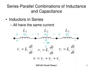
By KVL, the total voltage across the series combination is the sum of the individual voltages:
Factoring out the common term:
This is in the form , which shows us that the equivalent inductance is simply the sum.
Capacitors and Inductors in Series and Parallel (Circuits for Beginners #20)
Let's watch the segment on inductors from 'Capacitors and Inductors in Series and Parallel'.
Watch from 05:44 to 07:56. The video presents a brief geometric argument and then confirms the result with the KVL-based derivation we just performed.
For inductors in series, the equivalent inductance is:
This is a familiar rule: Inductors in series add, just like resistors in series.
Inductors in Parallel
When inductors are connected in parallel, they share the same voltage. The total current, by KCL, is the sum of the individual branch currents. Therefore, the rate of change of the total current is also the sum of the rates of change in each branch:
From the inductor equation, we can write . Since the voltage is the same for all parallel components, we can substitute this into our KCL equation:
Dividing by , we get the reciprocal formula.
Capacitors and Inductors in Series and Parallel (Circuits for Beginners #20)
Finally, let's watch the segment on parallel inductors.
Watch from 07:56 to 09:23. The narrator correctly points out that a simple geometric argument is tricky here, so the derivation relies purely on the voltage/current relationships we just discussed.
For inductors in parallel, the equivalent inductance is:
Inductors in parallel combine using the same reciprocal rule as resistors in parallel.
The following reading provides a good text-based summary of these rules for inductors.
This section from the 'Inductors' chapter provides a written summary of the series and parallel rules we have just derived.
Read the short section titled 'Series and Parallel Inductors'. This will reinforce the derivations and formulas.
3. Summary: The "Why" Behind the Rules
We've covered a lot of ground. The most important part is understanding why the rules are what they are. Let's summarize the rules and the physical reasoning in a table. This is a crucial piece of intuition for your exam preparation.
| Combination | Resistors (Energy Dissipation) | Capacitors (Electric Field) | Inductors (Magnetic Field) |
|---|---|---|---|
| Series | |||
| Reasoning | Adds opposition. All current must pass through every resistor. | Adds plate distance. This weakens the electric field for a given voltage, reducing capacitance. | Adds opposition to change. All inductors must oppose the same , so their opposing voltages add up. |
| Parallel | |||
| Reasoning | Adds paths. More paths for current to flow reduces total opposition. | Adds plate area. This allows more charge storage for a given voltage, increasing capacitance. | Divides the changing current. The total is split, so the overall voltage opposition is less. |
The key insight is that capacitors follow rules opposite to resistors because their behavior is dominated by physical dimensions (Area/Distance), whereas inductors follow the same rules as resistors because their behavior is dominated by their dynamic response to a common current (series) or voltage (parallel).
Conclusion
In this lesson, we derived the formulas for equivalent capacitance and inductance and, most importantly, explored the physical reasoning that explains why their combination rules differ from one another.
Key Takeaways:
- Capacitors in parallel add: (like resistors in series). This is because parallel connections effectively increase plate area.
- Capacitors in series combine via reciprocals: (like resistors in parallel). This is because series connections effectively increase plate distance.
- Inductors in series add: (like resistors in series). This is because their individual voltage drops (opposing current change) add up.
- Inductors in parallel combine via reciprocals: (like resistors in parallel). This is because the changing current is divided among them, reducing the overall opposition.
Preview of the Next Lesson:
We have now completed our foundational study of the three passive DC components: R, L, and C. Our next step is to venture into the world of time-varying signals. We will begin by learning how to describe sinusoidal signals using their key parameters: amplitude, frequency, period, and phase. This will lay the groundwork for analyzing how capacitors and inductors behave in AC circuits.