Recommended resources
The freely available resources this lesson will direct you to.
Hello!
In our last lesson, we explored our first energy storage device, the capacitor. We established that it stores energy in an electric field created by separated charges, with the core relationship being .
Today, we introduce the capacitor's counterpart: the inductor. While capacitors resist changes in voltage, inductors resist changes in current. They do this by storing energy, but in a magnetic field. This lesson will build the physical intuition behind this behavior, connecting it to the core equation that governs inductors. Your interest in the flow of energy and the physical "why" behind circuit laws will be central to our exploration.
This lesson covers the second learning outcome in our "Energy Storage Elements" module: Explain how an inductor stores energy in a magnetic field and use to relate its voltage to the rate of change of current.
1. The Inductor's Core Behavior: Electrical Inertia
At its simplest, an inductor is just a coil of wire. When current flows through this wire, it generates a magnetic field. The coil's shape concentrates this field, and it's this field that gives the inductor its unique property: it opposes any change in the current flowing through it.
Let's watch a short video that introduces this fundamental behavior.
The Hidden Power of Inductors — Why Coils Resist Change!
The video 'The Hidden Power of Inductors' by Prof MAD starts by demonstrating the core characteristic of an inductor: it acts as if it has inertia, smoothing out any sudden changes in current.
Watch the first 2 minutes and 27 seconds. Observe the difference between a circuit with just a bulb and one with an inductor added. Notice how the current doesn't jump instantly but rather ramps up and down gradually when the inductor is present.
This resistance to change is a form of electrical inertia. To build a strong mental model for this, a physical analogy is incredibly useful.
The Hidden Power of Inductors — Why Coils Resist Change!
The same video provides an excellent water-and-pistons analogy to explain this inertial effect. This should resonate with your preference for building physical intuition before diving into formulas.
Continue watching from 02:27 to 06:45. Pay close attention to the role of the heavy water wheel. Notice how it doesn't resist a steady flow but pushes back against any attempt to start, stop, or change the flow's rate. This is the key to understanding an inductor.
The key takeaway from the analogy is this:
- An inductor does not resist steady, constant current. In a DC circuit where the current is stable, an ideal inductor behaves just like a simple piece of wire.
- An inductor only resists a change in current. This is where its unique properties emerge.
2. The "Why": Energy in the Magnetic Field
So, what provides this "inertia"? The answer lies in the magnetic field.
When current flows through the inductor's coil, it creates a magnetic field. This field contains energy. To increase the current, you must supply extra energy to build up the magnetic field. Conversely, if you try to decrease the current, the magnetic field collapses and releases its stored energy, pushing the current along to try and keep it flowing.
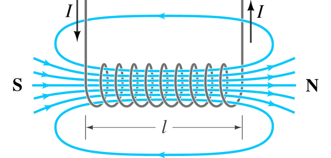
This process of storing and releasing energy from the magnetic field is the physical mechanism behind the inductor's opposition to current changes.
Inductors Explained - The basics how inductors work working principle
Let's see this process of energy storage and release in action.
Watch the segment from 04:14 to 07:15 in this video from The Engineering Mindset. It visualizes how the magnetic field builds up, stores energy, and then collapses, converting that stored magnetic energy back into electrical energy to push electrons. This is called 'back EMF' (electromotive force).
This behavior is governed by Lenz's Law, a fundamental principle in physics which states that an induced effect will always oppose the cause that produced it. In an inductor:
- When current increases, the inductor generates a voltage that pushes against the incoming current.
- When current decreases, the inductor generates a voltage that pushes in the same direction as the current, trying to keep it going.
3. Quantifying the Behavior: The Inductor's V-I Equation
We now have a solid conceptual model. Let's connect this physical behavior to a mathematical relationship. We've seen that the inductor's effect is tied not to the current itself, but to how it changes. This suggests a relationship involving a rate of change.
The voltage across an inductor is directly proportional to the rate of change of the current through it. This is the fundamental law for inductors:
Where:
- is the instantaneous voltage across the inductor in Volts (V).
- is the inductance of the coil in Henries (H). Inductance is a physical property determined by the coil's geometry (number of turns, length, area) and the material of its core.
- is the instantaneous rate of change of current in Amperes per second (A/s). It's a term from calculus representing the slope of the current-time graph.
Inductor Voltage and Current Relationship | Electronics Textbook
The textbook page 'Inductor Voltage and Current Relationship' from All About Circuits provides a clear, formal introduction to this equation and its components.
Read the first two sections, 'Inductor Voltage and Current Relationship' and 'Voltage Drop Across an Inductor with a Constant Current'. This will formally define the equation and immediately apply it to the simple case of constant DC current.
4. Applying the Equation: Key Scenarios
Let's use the equation to solidify your intuition for three critical scenarios.
Scenario 1: Constant Current (DC Steady-State)
In a DC circuit that has been running for a while, the current is constant.
- If the current is constant, its rate of change is zero.
- Therefore, the voltage across the inductor is Volts.
This is a crucial insight: In a DC steady-state, an ideal inductor acts like a short circuit (a zero-ohm wire).
Scenario 2: Linearly Changing Current
What if we force the current to increase at a constant rate (a straight, sloped line on a graph)?
- The rate of change is a constant, positive value (the slope of the line).
- Therefore, the voltage across the inductor is . A constantly changing current produces a constant voltage.

Scenario 3: Rapidly Changing Current
What happens if we try to change the current very quickly, for example by opening a switch?
- Opening a switch causes the current to drop from some value to zero in a tiny amount of time.
- This makes a very large negative number.
- The resulting voltage becomes a very large negative voltage spike. This is often called "inductive kickback" and can be powerful enough to create a spark or damage other circuit components.
Inductor Voltage and Current Relationship | Electronics Textbook
The 'All About Circuits' article has a great practical demonstration of this effect using a neon lamp that requires a high voltage to light up.
Read the sections 'Voltage Drop Across an Inductor With a Decreasing Current' and 'Voltage Drop Across an Inductor with Rapid Current Changes'. Note how opening the switch causes a huge voltage spike that is able to light the lamp.
5. Thought Experiment: Applying Your Knowledge
Let's test this new mental model. Imagine you connect an inductor to a voltage source that produces a square wave, flipping between +1V and -1V.
- During the +1V phase: The voltage
vis constant and positive. According to , what must the current be doing? - During the -1V phase: The voltage
vis constant and negative. What must the current be doing now?
Based on your answers, can you sketch the shape of the current waveform ? This is a great exercise in logical thinking about the component's behavior.
Click here to see the solution and explanation.
This is a classic problem that demonstrates the inductor's behavior.
- During the +1V phase: Since is constant and positive, must also be constant and positive. A constant rate of change means the current is increasing linearly—it's a straight-line ramp upwards.
- During the -1V phase: Since is constant and negative, must be constant and negative. This means the current is decreasing linearly—a straight-line ramp downwards.
Putting it together, the current waveform will be a triangle wave. The inductor "integrates" the voltage over time. When the voltage is constant positive, the current ramps up. When the voltage is constant negative, the current ramps down.
For a deeper dive into this specific example, you can review the "Example" section in the Inductor i-v equation in action article from Spinning Numbers (resource ID LINK).
Conclusion
In this lesson, we demystified the inductor, establishing it as a component that stores energy in a magnetic field and, as a result, opposes any change in current.
Key Takeaways:
- An inductor's primary characteristic is its resistance to changes in current, a property analogous to mechanical inertia.
- This behavior is due to energy being stored in and released from the magnetic field surrounding the coiled wire.
- The relationship between an inductor's voltage and current is defined by the rate of change: .
- Because of this relationship, a constant current (DC steady-state) produces zero voltage, making an ideal inductor behave like a short circuit.
- A rapid change in current can induce a very high voltage across an inductor.
Preview of the Next Lesson:
We have now established the fundamental behaviors of both capacitors and inductors. In the next lesson, we will quantify the energy they store by deriving and applying the formulas for capacitors and for inductors. We will also explore how to calculate the equivalent inductance and capacitance when these components are combined in series and parallel.