Recommended resources
The freely available resources this lesson will direct you to.
Hello! In our last lesson, we explored the inner workings of single-area OSPF, covering how routers discover neighbors, exchange their Link-State Databases (LSDBs), and use the SPF algorithm to calculate the best routes. This process works perfectly for many networks. But what happens when a network grows from dozens of routers to hundreds, or even thousands?
Today, we'll address that question by examining how OSPF scales to support very large networks. The learning outcome for this lesson is to explain the purpose of OSPF areas for creating a hierarchical network design. We will investigate the problems that arise in a large single-area network and see how segmenting the network into multiple areas provides a powerful and elegant solution.
The Challenge of Scale in a Single OSPF Area
As we learned, in a single OSPF area, every router must maintain an identical Link-State Database (LSDB) containing information about every other router and link in that area. While this provides a complete view of the topology, it becomes a significant burden in a large network.
This leads to three main problems:
- Huge Link-State Databases (LSDBs): Every router must store the entire topology map, consuming significant memory.
- Large Routing Tables: The complete map results in a route to every subnet, making the routing table unwieldy and potentially slowing down packet forwarding lookups.
- Frequent SPF Algorithm Recalculations: If any single link in the area flaps (goes down and up), every router in the area must recalculate its entire SPF tree. This consumes CPU cycles and can lead to network instability.
The video below explains these scalability challenges in more detail.
This video, "OSPF Multi Area Explained" from the CertBros channel, clearly outlines the problems that motivate the need for a multi-area design.
Watch the segment from 1:03 to 2:34 that discusses the issues of a large single-area OSPF network.
The core issue is that every router is burdened with detailed information about the entire network, even distant parts that might not be relevant to its local routing decisions. To manage this, OSPF introduces the concept of areas.
The Solution: A Two-Tier Hierarchical Design
To solve the scalability problem, OSPF allows you to divide a large network into smaller, more manageable pieces called areas. This creates a two-tier hierarchical design.
At the center of this design is Area 0, also known as the backbone area. All other areas, called non-backbone or regular areas, must connect directly to Area 0. This creates a "hub-and-spoke" or star topology from an area perspective, where Area 0 is the hub.
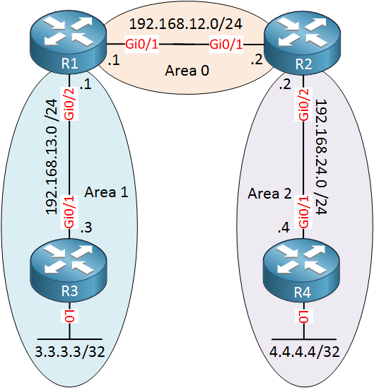
The most important rule in multi-area OSPF is: All traffic moving from one non-backbone area to another non-backbone area must pass through Area 0. For example, in the diagram above, traffic from R3 in Area 1 to R4 in Area 2 must travel through Area 0. A direct link between Area 1 and Area 2 would not be used for inter-area routing. This strict rule prevents routing loops in the inter-area design.
The following resource provides an excellent explanation of this hierarchical structure.
OSPF Area 0 and Multi-Area Structure
This article from learncisco.net clearly explains the mandatory role of Area 0 as the backbone and the hub-and-spoke nature of the design.
Read the first part of the article, from the beginning down to the section discussing traffic flow (ending just before the discussion of design perspectives). Focus on the "golden rule" that all non-backbone areas must connect to Area 0 and that inter-area traffic must traverse the backbone.
By creating this hierarchy, routers within a regular area only need to maintain a detailed LSDB for their own area. They receive summarized information about other areas, which is the key to scalability.
The Key Components: Router Roles and Summarization
This hierarchical design is made possible by different types of OSPF routers, each playing a specific role.
Area Border Routers (ABRs)
The most important router type in a multi-area design is the Area Border Router (ABR). As its name implies, an ABR is a router that sits on the border between areas.
- An ABR has interfaces in more than one area, with at least one interface always in Area 0. In the diagram above, R1 and R2 are ABRs.
- ABRs maintain a separate LSDB for each area they are connected to. For example, R1 maintains a full LSDB for Area 1 and a full LSDB for Area 0.
- The primary function of an ABR is to summarize routing information. It takes the detailed routes from a non-backbone area (like Area 1) and advertises a single summary route into the backbone (Area 0).
This summarization is what provides the major benefits of multi-area OSPF. It contains routing instability and reduces overhead. If a link inside Area 1 fails, only the routers within Area 1 need to run the SPF algorithm. Routers in Area 0 and Area 2 are unaffected because their summary route to Area 1, provided by the ABR, has not changed.
Other Router Types
For a complete picture, it's useful to know the other router roles:
- Backbone Routers: Any router with at least one interface in Area 0. All ABRs are, by definition, backbone routers.
- Internal Routers: A router with all of its interfaces inside a single non-backbone area. R3 and R4 in the diagram are internal routers.
- Autonomous System Boundary Routers (ASBRs): A router that connects the OSPF network to an external network, such as the internet or a network running a different routing protocol (like EIGRP). An ASBR performs redistribution, injecting external routes into OSPF.
The following video provides a clear overview of these router types and the crucial role of ABRs in summarization.
OSPF Areas and OSPF Types of Routers - Practical OSPF - Lesson 2
This video from the Practical Networking channel, "OSPF Areas and OSPF Types of Routers," gives a great explanation of the area hierarchy and the different router roles.
First, watch the segment explaining the two-tier hierarchy and the hub-and-spoke design. Then, continue watching the detailed breakdown of the four types of OSPF routers, paying close attention to the responsibilities of the ABR.
The Benefits of a Hierarchical Design
By implementing a multi-area design, we directly solve the scalability issues of a single large area.

The primary benefits are:
- Smaller Routing Tables: Routers in one area receive a summary of other areas, not every individual route.
- Smaller LSDBs: Routers only need to store the detailed topology for their own area.
- Improved Stability & Faster Convergence: A network change in one area does not trigger an SPF recalculation in other areas. This isolates instability and reduces the CPU load on routers across the network. Cisco recommends keeping the number of routers per area under 50 to minimize the computational load of the SPF algorithm.
Conclusion
In this lesson, we've seen how OSPF's hierarchical design using areas is a critical feature for building scalable, stable, and efficient networks. By moving from a flat, single-area topology to a structured multi-area design, we can manage network growth without overwhelming our routers.
Key Takeaways:
- Large single-area OSPF networks suffer from large routing tables, large LSDBs, and frequent, network-wide SPF calculations.
- Multi-area OSPF solves this with a two-tier hierarchy consisting of a central backbone (Area 0) and multiple non-backbone areas.
- All inter-area traffic must pass through Area 0, which creates a loop-free, hub-and-spoke design.
- Area Border Routers (ABRs) are the key components, connecting areas to the backbone and performing route summarization.
- This design results in smaller routing tables, smaller LSDBs, and isolates the impact of network changes, leading to a more stable and scalable network.
Now that we understand the architectural principles of both single-area and multi-area OSPF, our next step is to get hands-on. In the following lesson, we will begin configuring a foundational single-area OSPF network and verifying that routers are forming neighbor relationships correctly.