Recommended resources
The freely available resources this lesson will direct you to.
Hello! Last time, you traced the connections in a simple guitar booster and distinguished points on the same node from points separated by a component. Now you can put numbers on a simpler kind of schematic: a DC source and resistors. The goal is to calculate voltage, current, and resistance, then use Kirchhoff’s laws to check that the results make sense.
For now, we will treat sources and wires as ideal and resistors as having fixed values. That gives you a reliable foundation for analyzing the supply and resistor networks that appear in pedals. Allow about 40 minutes, including the video segments.
Three quantities, with the right units
Voltage is an electrical potential difference between two points. Current is the rate at which electric charge passes a point. Resistance describes how strongly a resistor opposes current. Their units are volts (V), amperes (A), and ohms (), respectively.
For a resistor, Ohm’s law relates all three:
The crucial qualification is that the voltage must be across the resistor whose resistance you use, and the current must be through that resistor. You cannot generally combine a voltage across an entire circuit with the resistance of just one of its parts.
Pedal calculations often use kilohms and milliamperes. Because and , these units pair conveniently: one milliampere through one kilohm produces a one-volt drop.
Watch the opening of Ohm’s Law from The Organic Chemistry Tutor for the units and the single-resistor calculation. The lesson will build on its series and parallel examples in separate segments below.
The opening of Ohm’s Law by The Organic Chemistry Tutor introduces the relationship between voltage, current, and resistance, then calculates current in a one-resistor circuit.
Watch the relationship for the quantities and units. Continue through the first example; notice that its source voltage is across the very resistor used in the calculation.
For instance, if a 9 V source is connected across a resistor, its current is
You can solve in the other direction. If a resistor has 6 V across it while carrying 2 mA, then
A voltage label always needs two points, even when one is implied. Saying “this node is at 6 V” usually means 6 V relative to the node chosen as 0 V, often labeled ground. It does not mean that the node possesses an absolute voltage on its own.
One path: series resistors and voltage around a loop
Resistors are in series when there is only one path through them: current cannot split between one resistor and the next. The same current therefore passes through each. Their equivalent resistance—the single resistance that would draw the same current from the source—is their sum:
Watch the series portion of the video before examining a second circuit below.
The video extends Ohm’s law to three series resistors, finding total resistance and current before calculating each voltage drop.
Watch total resistance and current, then voltage drops. Focus on why the source voltage is paired with total resistance, whereas each individual drop is paired with its own resistor.
The following schematic gives us labelled nodes and polarities to calculate. Its 45 V source is an example for analysis, not a suggested pedal supply.
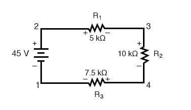
There is no branch, so first combine the resistances and find the current through every resistor:
Now use that same current with each individual resistance:
The current need not “use up” as it passes the resistors. What changes is the potential. Choose node 1, at the source’s negative terminal, as 0 V. Node 2 is then at 45 V; crossing in the direction of conventional current brings us to 35 V at node 3; crossing brings us to 15 V at node 4; and crossing returns us to 0 V. That also explains the polarity drawn on : its right side is at the higher potential.
This is Kirchhoff’s voltage law (KVL): the signed voltage changes around any closed loop sum to zero. Going from the source’s negative terminal to its positive terminal is a rise; crossing these resistors in the direction of current is a drop:
You may choose the opposite direction around the loop. The signs all reverse, but the balance still holds. KVL is not restricted to series circuits; it applies to any closed path in a circuit.
Branches: current at a node
Recall the booster schematic’s junctions: several component terminals could meet at one node. Current arriving at such a node may divide among branches. Kirchhoff’s current law (KCL) says that, for a steady-state circuit, total current entering a node equals total current leaving it. For example, if 3 mA enters and one branch takes 1 mA, the other branches together must take 2 mA.
Watch the parallel example in the final segment of the video.
The final segment contrasts series and parallel resistors, then uses Kirchhoff’s current law to account for current at junctions.
Watch parallel branches for why each branch has the same voltage but can carry a different current. Continue through junction currents to see incoming current balance outgoing current.
Two resistors are in parallel if each terminal of one connects to the same respective node as a terminal of the other. They therefore have the same voltage across them, although their currents can differ. Put a and a resistor in parallel across 6 V. Ohm’s law gives
KCL says the source supplies their combined 3 mA. An equivalent single resistor drawing 3 mA across 6 V would have resistance
More generally, applying KCL and Ohm’s law to parallel branches gives
Parallel equivalent resistance is smaller than the smallest branch resistance: adding another path allows more total current at the same voltage. This is the opposite of adding resistors in series, which increases total resistance.
Putting the laws together
A small network can contain both arrangements. Suppose a 9 V source feeds a resistor, after which the path splits into and branches that rejoin at the source’s negative terminal. We already know the parallel pair is equivalent to . The source thus sees a resistor in series with that equivalent resistance:
All 3 mA pass through the resistor before the split, producing a 3 V drop. KVL then tells us that 6 V remains across the parallel branches. Their currents are 2 mA and 1 mA, as calculated above; KCL confirms that they add to the incoming 3 mA. Both laws describe the same network, from different perspectives.
This gives you a dependable order of attack: identify nodes and branches; combine resistances where the series or parallel connection is clear; use the source voltage and total resistance for source current; then work back through individual components using Ohm’s law. Check junction currents with KCL and closed-loop voltages with KVL. If a computed current is negative, it may simply flow opposite to the direction you assumed—but first check your node connections, units, and signs.
What to carry forward
Ohm’s law connects a resistor’s own voltage, current, and resistance. Series components share current; parallel components share voltage. KCL balances current at a node, while KVL balances voltage changes around a closed loop. Together, these rules let you calculate unknown quantities and catch mistakes rather than relying on a formula alone.
The next lesson uses these foundations to calculate the voltage at the junction of two resistors—and what happens when another circuit is connected to that junction.