Recommended resources
The freely available resources this lesson will direct you to.
Hello! In the previous lesson, you used Ohm’s law to calculate resistor voltages and used Kirchhoff’s laws to check currents at branches. Now we’ll apply those same ideas to a common pedal circuit: two resistors that create a chosen voltage between the supply and ground.
The important question is not just “What voltage does the divider produce?” but “Does it still produce that voltage after another circuit is connected?” By the end of this lesson, you’ll be able to calculate both answers. Allow about 40 minutes for the lesson, video segments, and short reading.
The output is a voltage across the lower resistor
A resistor divider has an upper resistor between the supply and an output node, and a lower resistor between that node and ground. is the output node’s voltage relative to ground. The left-hand circuit below shows this arrangement.
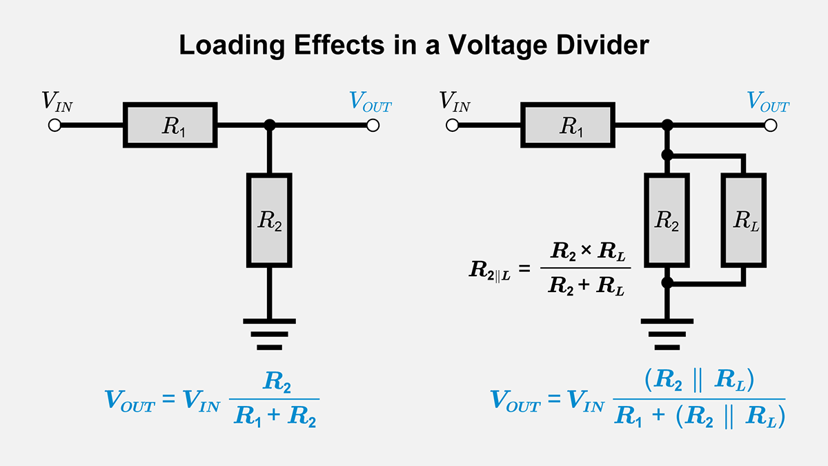
“Unloaded” does not mean that no current flows. Current still travels through both divider resistors. It means that nothing connected to the output node draws additional current.
Watch the opening of Voltage Divider Circuit Explained! from The Organic Chemistry Tutor. It connects the series-circuit calculation from the previous lesson to the divider shortcut.
Voltage Divider Circuit Explained!
The Organic Chemistry Tutor’s Voltage Divider Circuit Explained! derives the unloaded result using current and Ohm’s law.
Watch the basic divider. Notice that the voltage called the output is the voltage across the lower resistor, not across the upper one.
Because an unloaded divider has only one current path, the same current flows through and :
The output is the voltage across , so Ohm’s law gives
The fraction is the divider ratio. Its placement matters: is in the numerator because we measure the output across . If the resistors are equal, the output is half the input. If is made larger relative to , the output moves closer to the input voltage.
For example, two resistors across a 9 V supply give
The current through the pair is . That current flows even if the output node is left unconnected. This midpoint can be useful in a single-supply pedal circuit, but 4.5 V is the unloaded prediction, not a guarantee under every connection.
Connecting a load changes the circuit
Suppose another part of the circuit connects between the output node and ground. For now, represent what it draws by a resistor , called the load. As the right-hand circuit in the image shows, and touch the same two nodes. They are therefore in parallel.
Current arriving through now splits: some passes through , and some passes through . Kirchhoff’s current law says
That is why we cannot keep using : and no longer carry the same current.
Watch the video’s loading example next. It demonstrates both a modest change and a severe one as the load resistance changes.
Voltage Divider Circuit Explained!
The loading segment of Voltage Divider Circuit Explained! shows why adding a device across the lower resistor changes the output calculation.
Watch the loaded examples. Focus on the connection across the lower resistor, the parallel-equivalent calculation beginning around 00:09:45, and the comparison between the outputs for two different load resistances.
The calculation is a two-step reuse of what you already know. First replace the parallel pair with its equivalent resistance:
Then treat and this effective lower resistance as a divider:
This formula applies when connects from the output node to ground, across . It is not a rule for every possible way of connecting another component.
Calculate and check a loaded 9 V divider
Return to the two resistors that gave 4.5 V unloaded. Now connect a load from the output to ground. The two lower resistors are equal, so their parallel equivalent is :
The new output voltage is
The original 4.5 V answer was correct before the load was attached. Applying it afterward would miss a 1.5 V change.
We can check the result without trusting the divider formula alone. The voltage across is , so . Both lower resistors have 3 V across them, giving and . The two branch currents add to , exactly the current entering the node.
For another numerical view of the same method, read the loading example in TechWeb’s Voltage Divider Circuit. It uses different resistor values and compares the intended unloaded voltage with the loaded result.
Voltage Divider Circuit | DC Circuits Fundamentals: Article Guide | TechWeb
Read TechWeb’s explanation to see the parallel-lower-resistor method applied to a second set of numbers.
Under “Practical Considerations in Voltage Divider Design,” go to “Loading Effect,” then “Accounting for Real-World Load.” Read the loading example, from the description of a load across R_2 through the comparison of approximately 2.65 V loaded with 3 V unloaded. Focus on which resistance is replaced before the divider equation is used.
How much loading is acceptable?
A parallel resistance is smaller than either resistor in the pair. Thus, when a finite resistive load is placed across , the effective lower resistance falls. With a positive fixed supply and ordinary positive resistors, the output voltage falls too.
The size of the change depends on the load. Keep the 9 V divider with , but make the load instead:
That is much closer to the unloaded 4.5 V than the 3 V obtained with a load. A larger load resistance draws less current from the output node and disturbs the divider less. In the limiting case of no external current draw, the loaded calculation becomes the unloaded one.
There is a practical trade-off. Making both divider resistors smaller while preserving their ratio keeps the unloaded voltage the same, but usually makes a fixed resistive load disturb it less. It also makes the divider draw more current from the supply. That matters in a battery-powered pedal. Conversely, a circuit with a high input resistance can often take a voltage from a divider while drawing little current from its output. We will study such circuit inputs in later modules; for now, the resistor is our calculation model.
Keep this distinction in mind: a divider sets a voltage according to its entire connected network. The resistor ratio alone determines the output only when the output draws no additional current, or when loading is small enough that the unloaded result is an acceptable approximation.
What to carry forward
For an unloaded two-resistor divider, find the series current or use . For a loaded divider with a resistor from output to ground, first calculate , then use that value as the lower leg. Check that parallel branches share the calculated output voltage and that their currents add at the junction.
In the next lesson, you’ll distinguish a pedal circuit’s steady DC voltage—such as a divider-produced midpoint—from the changing audio signal that can be superimposed on it.