Recommended resources
The freely available resources this lesson will direct you to.
- Industrial Relay Control System | Wiring a 24 Volt DC Relay Circuitwww.youtube.com
- How to Read Electrical Diagrams | Wiring Diagrams Explained | Control Panel Wiring Diagramwww.youtube.com
- [PDF] InstallatIon and WIrIng Chapter Chapter Chapter - AutomationDirectcdn.automationdirect.com
- 4. Start/Stop Seal-In Circuit Explained for Industrial Motor Control (4 of 22) – JoeGuardian Automationjoeguardian.com
Hello again. In the previous lesson, you learned to recognize a supply, switch contacts, a relay coil, and a load on a schematic. Today the question changes from “What is this symbol?” to “Is there a complete path for current?” We will trace one 24 V DC circuit through its switching devices, follow its return path, and explain why its lamp stays on after the Start button is released.
Start with a complete path
A control load operates when the circuit provides a path from one side of its supply, through the load, back to the other side. In a 24 V DC schematic, that often means tracing from +24 V through contacts to a coil or lamp, then back to 0 V. An open contact anywhere in that particular path interrupts it.
Use three questions as you follow a line on a schematic:
- Where does this path get its supply?
- Which contacts must be closed for it to reach the load?
- How does it return to the supply?
A schematic shows electrical relationships, not necessarily the physical route each wire takes inside a panel. It may also omit upstream equipment. If you cannot find a power supply or protective device on the portion shown, do not assume one is absent from the installation; it may be on another drawing.
Watch this short relay demonstration before examining our circuit. Notice that supplying the coil changes the relay’s state; removing that supply lets it return to its normal state. The terminal numbers belong to the particular relay being demonstrated, not to every relay.
Industrial Relay Control System | Wiring a 24 Volt DC Relay Circuit
In “Industrial Relay Control System | Wiring a 24 Volt DC Relay Circuit,” SolisPLC demonstrates what energizing a relay coil does. Watch it to connect the schematic idea of a coil with a physical relay changing state.
In the coil-connection demonstration, watch coil energization: the presenter connects the supply, observes the relay respond, then removes the connection. Focus on the change in state rather than the relay’s particular terminal numbers.
Read the first rung: the relay-coil path
The diagram below is our main example. It uses its own drawing conventions and labels rather than serving as an IEC symbol chart. Its left rail is marked 24VDC, and its right rail is marked GND. For tracing this drawing, treat GND as the depicted return to the DC supply; the drawing alone does not establish whether that return is bonded to protective earth.
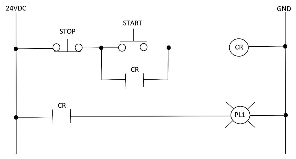
Begin at the 24VDC rail on the upper rung and move right. The Stop pushbutton is normally closed: when no one is pressing it, its contact allows a path onward. Next comes a split. The upper branch passes through the normally open Start pushbutton; the lower branch passes through a normally open contact labelled CR. The branches rejoin before the CR coil, whose other side connects to the right-hand return rail.
The dots at the branch points matter: they show where the conductors join. The Start contact and the CR contact are parallel alternatives. At least one must be closed to carry current across that part of the rung. Stop is in series with both alternatives, so pressing Stop interrupts either route to the coil.
At rest, Start and the CR contact are open. Although Stop is closed, neither branch across the split is complete. The CR coil is therefore de-energized. Pressing Start closes one branch. You can now trace a complete route: from the left supply rail, through Stop and Start, through the CR coil, to the right-hand return rail. Current can flow, and the coil energizes.
Notice what does not happen: current does not have to pass through both Start and the parallel CR contact. When two branches rejoin, trace each available route through the split separately.
Why releasing Start does not turn it off
CR appears more than once on the diagram. The circle marked CR on the upper rung is the relay coil. The contacts marked CR are operated by that same relay, even though schematic lines do not run from the coil to each contact. The shared tag expresses their mechanical relationship.
As soon as the CR coil energizes, its normally open contact beneath Start closes. Releasing Start opens the Start branch again, but the closed CR contact now provides another route around it. This is a seal-in, or latching, control path: the relay keeps its own coil supplied through one of its contacts. It is not a permanently stored state. If the coil loses power, the contact returns to normal and the seal-in path opens.
The reading below presents the same start-stop principle in a motor-starter example. Its load is a starter coil, and it includes an overload contact that is not shown in our image. Concentrate on what changes as Start is pressed and released, then as Stop is pressed; do not add the example’s overload contact to the pictured circuit.
Read JoeGuardian Automation’s explanation of a start-stop seal-in circuit to reinforce the difference between the momentary Start path and the contact that keeps a coil energized afterward.
In “Basic Ladder Diagram,” begin at the sentence introducing the “OR condition.” Read the operating sequence through the end of “Sequence of Operation,” Step 5. Follow which of the two parallel paths is available at each stage, and identify the moment when neither path remains available.
Pressing Stop opens a contact before the two branches. Neither Start nor the CR seal-in contact can bypass it. The CR coil loses its path to the supply and de-energizes; its normally open contacts return to open. Releasing Stop closes the Stop contact again, but does not restart the relay: Start and the CR seal-in contact are now both open. Under the normal operation shown, a fresh Start press is required.
Read the second rung: the lamp path
The lower rung begins at the same left-hand supply rail but has its own route across the page: through a normally open CR contact, through pilot lamp PL1, and back to the right-hand return rail.
When CR is de-energized, this contact is open, so PL1 is off. When the upper rung energizes the CR coil, this contact closes. The lower rung then has a complete supply-to-return path through PL1, and the lamp lights. Pressing Stop breaks the coil’s path on the upper rung. Once CR drops out, its lower-rung contact opens and PL1 goes off.
This distinction is useful: PL1 is not in series with the CR coil. Stop does not appear on the lamp rung. Instead, Stop affects the lamp indirectly by causing the CR coil—and therefore its lamp-switching contact—to change state. Similarly, the lower CR contact does not itself “make” 24 V; it permits or interrupts a path from the rail that is already supplied.
Here is the normal operating sequence in one view. “Closed” and “open” describe the contacts’ states at that moment, not just whether they are called normally closed or normally open.
| Moment | Stop | Start | CR seal-in contact | CR coil | PL1 |
|---|---|---|---|---|---|
| At rest | Closed | Open | Open | Off | Off |
| Start held | Closed | Closed | Closes as CR energizes | On | On |
| Start released | Closed | Open | Closed | On | On |
| Stop pressed | Open | Either | Opens as CR drops out | Off | Off |
| Stop released | Closed | Open | Open | Off | Off |
The table describes the intended sequence, not every possible fault or the brief time a real relay takes to move. Its main value is to keep the contact state separate from the button’s normal designation: a normally open Start contact is closed while the button is pressed.
A tracing habit you can carry to other drawings
For each load on a schematic, trace one complete circuit at a time. In this example, tracing the CR coil tells you when the relay operates; tracing PL1 separately tells you when the indication operates. Then use their shared CR tag to connect the two explanations.
If an intended load is off, the same method helps you reason about where its path might be incomplete. For instance, if CR stays energized after Start is released but PL1 remains dark, the Start and seal-in paths have evidently done their job under the behavior shown; attention shifts to the lower-rung path or lamp. That is a deduction from the schematic, not a diagnosis of a particular physical component. Study such cases on paper or in a simulator. Inspection, measurement, or alteration of a real panel requires appropriate authorization and safe isolation procedures.
Conclusion
To trace a 24 V DC control circuit, find the supply and return, then follow a complete path through closed contacts to each load. Series contacts can interrupt a path; parallel contacts provide alternative routes. In our example, Start initially energizes the CR coil, a CR contact keeps it energized after Start is released, and a different CR contact switches PL1. Stop opens the path shared by both routes to the coil, so the relay and lamp turn off.
Next, you will connect this schematic way of thinking to a PLC input/output list, matching signals to physical terminals, field devices, and panel wiring.