Recommended resources
The freely available resources this lesson will direct you to.
- How to Read Electrical Diagrams | Wiring Diagrams Explained | Control Panel Wiring Diagramwww.youtube.com
- Electrical Symbols Explained (Beginner's Guide to Ladder Logic)www.youtube.com
- IEC 60617 Electrical Symbols: 114 Free UK SVGs | Elec-Matewww.elec-mate.com
- ANSI vs IEC Electrical Symbols Chart | Industrial Controlsviox.com
Hello again. Last time, you learned to choose a drawing by the question it answers: a single-line diagram shows major power relationships, while a control schematic shows how a circuit works. Now we will look inside those drawings. This lesson connects common panel hardware—breakers, contactors, relays, power supplies, terminals, sensors, and loads—to the IEC-style symbols and labels used to represent it.
You do not need to memorize an entire symbol library. The useful first skill is to recognize a symbol’s function, then use its tag, terminal markings, and drawing legend to identify the particular device.
A symbol is a function, not a picture of the hardware
Look at this industrial-panel single-line diagram. On the left, protective devices and contactors feed three motors. Toward the upper right, a power supply provides 24 V DC for the PLC and control equipment. The components are recognizable by both their graphical forms and labels such as CB4, K1, PS1, and M1.
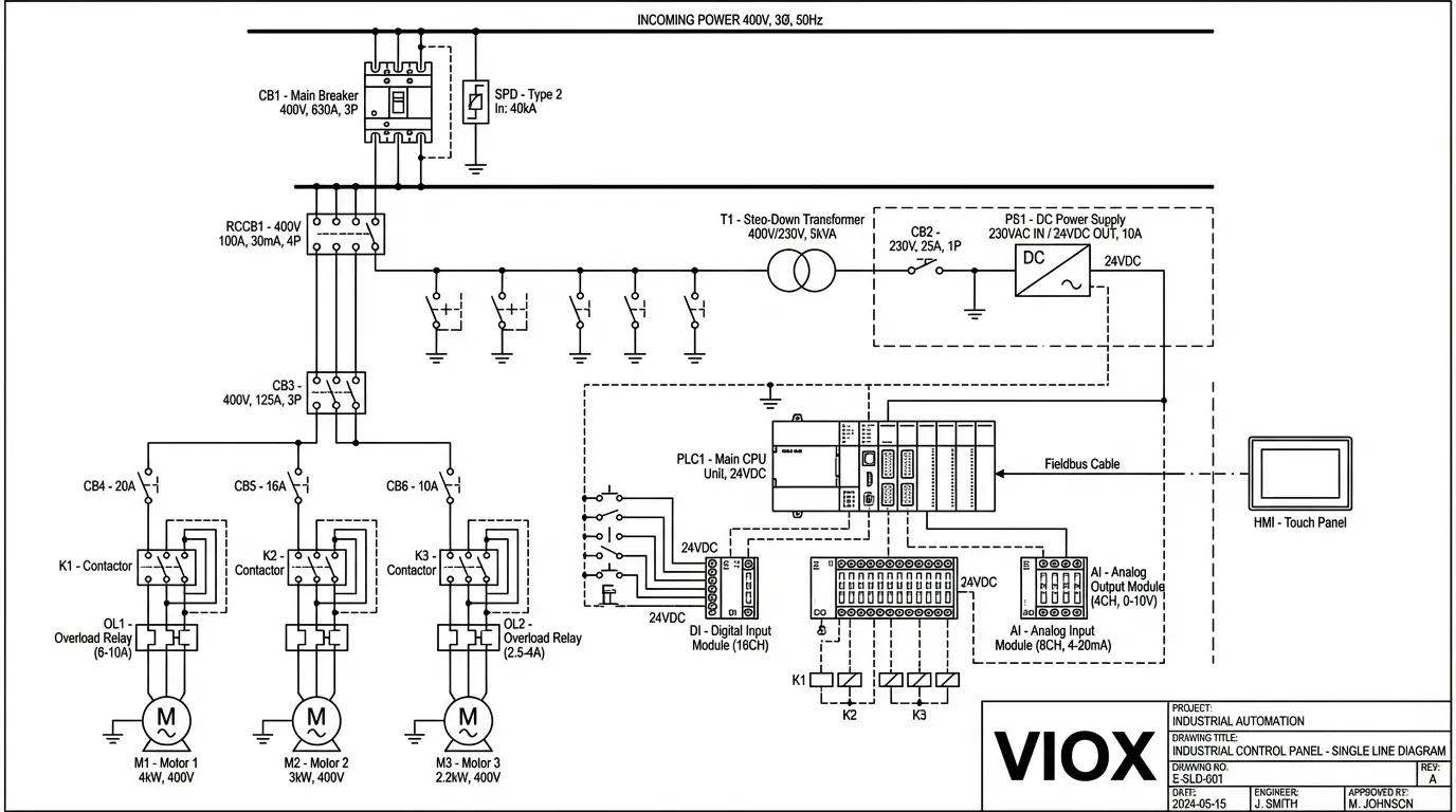
This is a project drawing, not a definitive IEC symbol chart. Its labels help us follow real equipment, but another drawing package might draw a device somewhat differently or use different tag letters. IEC-style symbols provide a common graphical language; the project’s legend tells you how that language is used on a particular set of drawings.
A practical way to read an unfamiliar symbol is to separate four clues:
- Shape: Does it depict a switch contact, coil, protective device, connection point, or load?
- Tag: Which device does it belong to? For example, several symbols marked K1 may represent parts of one contactor.
- Terminal markings: Where would a conductor connect to the physical device?
- Notes and normal condition: Is a contact shown with its actuator at rest, its coil de-energized, or under another stated condition?
The shape alone often cannot distinguish a control-relay contact from a contactor’s auxiliary contact. Their tags and the drawing legend supply that identity.
Protection and connection: MCBs and terminal blocks
An MCB (miniature circuit breaker) is an overcurrent protective device. In a schematic, look for a circuit-breaker symbol in the conductor path: a switching contact with a marking that distinguishes its automatic tripping function from a plain switch or isolator. A multi-pole breaker may be represented with several linked poles. Its symbol does not tell you its current rating, trip characteristic, or whether it is suitable for a particular installation; those require annotations and equipment data.
Do not confuse the MCB with a fuse, generally represented by a small element in the conductor path, or with a contactor, whose contacts are operated by a coil. They can all interrupt a path, but they have different jobs. A contactor is not, by itself, a substitute for the specified overcurrent protection.
A terminal block does a different job again: it provides a defined place to join conductors, often at the boundary between panel wiring and field wiring. On a schematic, a terminal is shown as a marked connection point along the circuit, with an identifier such as X1:2 (terminal 2 on strip X1). The precise terminal glyph varies between drawing libraries. Its identifier matters: a plain junction dot means connected conductors, but it does not by itself identify a physical terminal where someone can land a wire.
Read the following chart as a recognition guide, not a specification for selecting protective equipment.
ANSI vs IEC Electrical Symbols Chart | Industrial Controls
VIOX groups terminals, circuit breakers, fuses, and indicating lights together. Use its IEC column to compare their different graphical roles.
In “Signal, Connection, and Protection Symbols,” begin with the sentence introducing devices that “indicate status, connect conductors, or interrupt abnormal current.” Read the symbol group through the circuit-breaker bullet. Focus on why a terminal symbol identifies a connection point but not its terminal number, and why a breaker symbol does not identify its rating. The fuse bullet immediately afterward is optional for this lesson.
In the single-line diagram, CB4 precedes K1 on the first motor branch. Read that as protective equipment followed by switching equipment; do not infer their full specifications from the abbreviations or shapes alone. The next course module will teach you to draw such elements precisely in CAD, but recognition comes first.
One electromagnetic device can have several symbols
A contactor is a switch operated by an electromagnetic coil. IEC-style control schematics commonly draw the coil as a rectangle, labelled with a device tag and often terminals A1 and A2. Its main contacts, which switch a load such as a motor, appear as separate contact symbols. Its auxiliary contacts, used for control or indication, may appear somewhere else again. All belong to the same physical contactor when their tags and cross-references say they do.
A control relay follows the same representational idea: a coil and one or more contacts. A basic relay coil and contactor coil can look alike; so can their auxiliary contacts. The distinction comes from the device tag, legend, description, and what the contacts are specified to switch—not from assuming every contactor contact has a unique outline.
Contacts are usually shown in their normal, unactuated state. For an ordinary relay or contactor, this commonly means the coil is de-energized:
- A normally open (N.O.) contact has a gap in that state; operating its device closes it.
- A normally closed (N.C.) contact makes a connection in that state; operating its device opens it.
The image makes an important point: its contactor and control-relay rows use the same basic contact shapes within each drawing style.
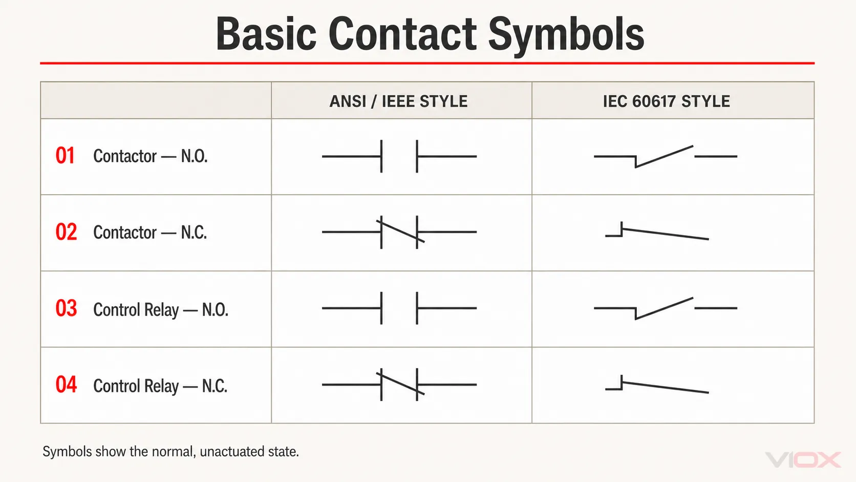
Read the contact section below, concentrating on the IEC column, rather than trying to combine the IEC and ANSI/IEEE drawings into one notation.
ANSI vs IEC Electrical Symbols Chart | Industrial Controls
VIOX explains why contact shape is only one of several clues needed to identify a device. This is especially useful when a coil and its contacts appear far apart on a drawing.
Start just before “Basic Contact Symbols: N.O. and N.C.” at the opening sentence about a symbol not giving enough information by itself. Read contacts and tags through the paragraph following the N.O./N.C. comparison. Focus on the four-layer table and on why the contactor and relay contacts cannot be distinguished by contact shape alone.
The same idea appears in a real schematic walkthrough. Watch Upmation point out the legend first, then identify a relay coil and its contacts using the device designation and cross-references.
How to Read Electrical Diagrams | Wiring Diagrams Explained | Control Panel Wiring Diagram
In “How to Read Electrical Diagrams,” Upmation shows why a drawing’s legend is worth consulting before interpreting its symbols.
Watch the legend for examples of a motor, solenoid valve, and contactor, and for the warning that CAD libraries may differ. Then watch relay cross-references: notice how the tag and contact references link a coil to N.O. and N.C. contacts elsewhere on the drawing.
For now, remember the relationship rather than the page location: K1’s coil and K1’s contacts represent different functions of the same tagged device. Later, when we trace a complete circuit, we will use those symbols to explain precisely when a load receives power.
Power supplies: recognize the conversion and its terminals
Many panels use a 24 V DC power supply to power control equipment. Unlike a simple contact, a supply has an input side and an output side. On an IEC-style schematic it may be represented as a labelled functional block showing AC input and DC output, rather than as one universal, easily memorized glyph. Look for annotations such as AC/DC, an input voltage, +24 V, and 0 V, then check the drawn terminal designations.
In the single-line image, PS1 is labelled as a power supply with 230 V AC input and 24 V DC output. Nearby, CB2 protects its incoming branch. The symbol and label establish the conversion function; they do not establish the supply’s output capacity or every detail of its protective arrangement.
Keep three markings distinct when reading a drawing:
- +24 V and 0 V identify the two sides of a DC supply circuit.
- PE identifies protective earth.
- Whether a project bonds 0 V to PE is a design detail to verify, not something to assume because both appear near the supply.
This is one reason labels are as important as shapes. A generic power-supply block becomes meaningful when you know which terminals are AC inputs, which are DC outputs, and which project device the block represents.
Sensors report conditions; actuators do something with power
A sensor detects a condition. How it appears in a schematic depends on what kind of signal it provides.
A limit switch responds to physical movement, such as a machine part pressing a plunger. You may see an N.O. or N.C. contact symbol with a mechanical-actuation marking. A pressure or level switch likewise uses contact action plus an indication of what operates it. First identify the sensed condition; then identify the contact’s state under the drawing’s stated normal condition.
An electronic proximity sensor may instead appear as a sensor block with supply and signal connections. It is unsafe to treat every sensor as a simple dry contact: some need power, and their output type must be identified from the drawing and device information. An analog sensor may have a signal value rather than a simple open-or-closed output. At this stage, the essential mapping is sensor function and its shown connections, not its internal sensing technology.
An actuator converts an electrical command into action or a visible result. Common schematic representations include a solenoid coil, a motor symbol (often a circle containing M), and an indicating lamp symbol. A solenoid may operate a valve; its electrical coil symbol does not, by itself, explain the valve’s full pneumatic or hydraulic behavior. A motor symbol identifies the load, not the contactor that switches its supply. An indicating lamp marks a signalling function; its color and voltage still need labels or other documentation.
The next section of the VIOX guide places sensor-switch symbols alongside coil and actuator symbols. Study the families of shapes and qualifiers rather than trying to memorize every variation.
ANSI vs IEC Electrical Symbols Chart | Industrial Controls
VIOX compares sensors operated by process conditions or movement, then introduces IEC-style coils and actuators. It also explains why separate coil and contact symbols must be linked by their designation.
Read “Sensor and Process Switch Symbols” from its explanation of contact symbols with qualifiers, then continue through “Coil and Actuator Symbols” to the warning about similarly shaped coils. This is sensors and coils. In the sensor chart, identify what operates each example; in the coil chart, focus on the IEC column and the role of the device tag.
Put the mappings together
Imagine finding the following labels in the small pump panel introduced last lesson. They are illustrative project labels, not mandatory IEC tag letters.
| Hardware you are looking for | What to seek on the schematic |
|---|---|
| MCB QF1 | A tagged circuit-breaker symbol in the supplied conductor path |
| 24 V DC supply PS1 | A labelled AC-input/DC-output supply block and its terminals |
| Field limit switch S1 | A mechanically operated contact, with its normal state shown |
| Contactor K1 | A coil symbol plus separately drawn, identically tagged contacts |
| Control relay K2 | A coil and its tagged control contacts, identified by the legend |
| Terminal X1:2 | A marked connection point belonging to terminal strip X1 |
| Solenoid Y1 | A tagged electrical actuator coil |
| Pump motor M1 | A motor/load symbol, distinct from K1’s coil and contacts |
Suppose the drawing shows K1 beside a rectangular coil in the control circuit and beside three switching contacts in the motor-power circuit. That is not necessarily four devices. The shared tag tells you to investigate them as parts of one contactor. Conversely, two identical-looking rectangles with different tags must not be assumed to be the same coil.
This method works even when a library’s symbol differs slightly from an example you learned: identify the function, verify the tag, inspect terminal markings, and consult the project legend. Do not use a training illustration alone to select equipment or work on a live panel.
Conclusion
Common panel components map to functional symbol families: breakers protect, supply blocks convert power, terminals identify connection points, contacts switch, coils operate relays and contactors, sensors report conditions, and actuator symbols identify loads that respond. The most important habit is to read each shape together with its tag, terminals, and legend. A contact symbol tells you its normal state; it cannot, by itself, tell you which physical device owns it.
Next, we will use these symbols to trace a 24 V DC control circuit from its supply, through switching devices, to a load and back.