Recommended resources
The freely available resources this lesson will direct you to.
Hello, and welcome. This course begins with the documents used to describe a control panel, before moving into CAD drafting, PLC programming, and testing. You do not need to know electrical symbols yet. For now, the important skill is knowing which drawing can answer which question.
Imagine a small panel that controls a pump motor. You might want to know where its power comes from, what makes it run, where a field switch connects, or where the contactor sits inside the cabinet. Those are different questions, and no single drawing answers all of them well. By the end of this lesson, you should be able to choose between a single-line diagram, control schematic, wiring diagram, terminal plan, and panel layout.
One panel, several views
The image below shows how the same electrical project can be presented as physical panel views and circuit drawings. Notice the contrast between the views showing where equipment is placed and those showing electrical relationships. It is not an example of all five drawing types we will study.
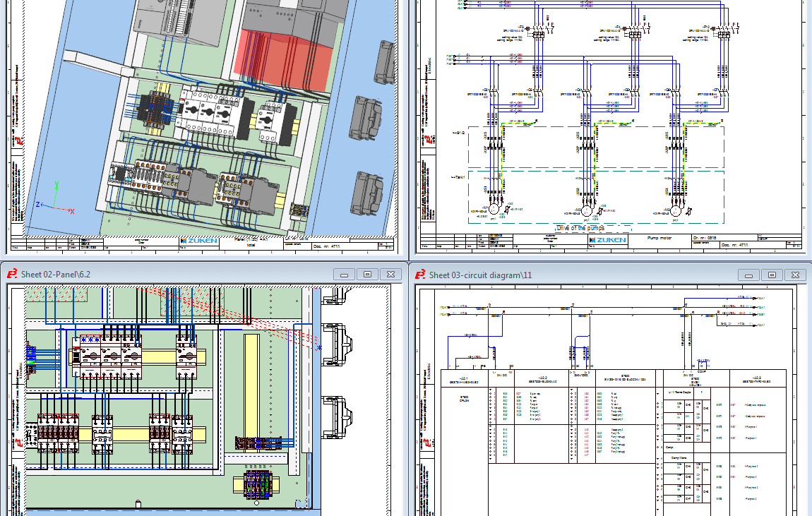
Think of a drawing package as a set of answers, each at a different level of detail. A single-line diagram gives an overview of power distribution. A control schematic explains how a circuit operates. Wiring and terminal documents identify connections to make or check. A panel layout establishes physical placement.
Read the following overview first. You do not need to memorize the symbols or conductor-size examples; concentrate on what each drawing includes and leaves out.
Electrical Drawing: Types, Symbols & How to Read Them
Read “Electrical Drawing: Types, Symbols & How to Read Them” from Industrial Control Academy for its comparison of drawing purposes.
Under “What Are the Main Types of Electrical Drawings?”, scan the summary table. Then read “Schematic Diagrams and Ladder Diagrams” through “Wiring Diagrams,” from function to connections. In “Single Line and Three Line Diagrams,” read from the definition of a single-line diagram through the explanation of a three-line diagram, the power overview. Skip the subsequent cable-sizing example for now. Finally, under “Layout, Block, and Interconnection Diagrams,” read the layout comparison. Ask what physical details each view does not promise to show.
One qualification matters throughout this lesson: drawing names and conventions vary between companies. A schematic can carry wire and terminal labels; a wiring diagram can show more or less routing detail. Identify a sheet by its purpose and content, not its title alone.
The single-line diagram: the power-system overview
Suppose our pump has a three-phase motor. Before examining individual control wires, a designer or technician needs a broad answer: What supplies the motor, and what major devices lie between the supply and the motor?
A single-line diagram, also called a one-line diagram or SLD, compresses that power path. One line can stand for a set of conductors rather than one literal wire. On a small motor-panel SLD, you might find the supply, main protective device, motor starter, and motor, with relevant voltage or equipment ratings. You would not expect it to specify every control contact, individual terminal landing, or component position on the mounting plate.
Watch Electric Rob turn a circuit with separate conductors into a one-line representation. The useful insight is what the simplified line preserves—and what a reader must look up elsewhere.
ELECTRICAL ENGINEER Explains Single Line Diagrams
Watch “ELECTRICAL ENGINEER Explains Single Line Diagrams” by Electric Rob to see why a one-line is an overview rather than a wire-by-wire drawing.
In the definition, listen for what the single line represents. Then watch the conversion from a battery, fuse, switch, and lamp circuit to a one-line. Focus on which conductors are no longer drawn separately and why the detailed drawing may still be needed.
For our pump, the SLD is the right first sheet if someone asks, “Which supply and major protective equipment feed this motor?” It is the wrong sheet if they ask, “Which terminal receives the wire from the field switch?”
The control schematic: why the circuit works
Now change the question: What must happen before the pump contactor energizes? That calls for a control schematic. It represents components by electrical symbols and shows their functional connections. In motor control, this is often drawn as a ladder-style schematic. Its arrangement makes it possible to follow a control path, but it does not tell you where the devices are mounted or how a cable travels through the cabinet.
Consider a deliberately simplified 24 V DC example. A protected supply feeds a maintained field switch, which controls a contactor coil; the other side of the coil returns to the supply. The schematic lets you reason that closing the switch completes the coil circuit. The contactor’s power contacts, which switch the motor supply, may appear elsewhere on the drawings even though they belong to the same physical device. We will learn to trace such circuits carefully in a later lesson.
This example explains a drawing purpose, not a design to build: a real pump system needs requirements, appropriate protection, and a separately considered safety design.
A schematic can include device tags, wire numbers, terminals, and cross-references. Those annotations make it more useful, but its central question remains “How is this electrically meant to work?” The distance between two symbols on the page does not tell you the distance between the corresponding devices.
Wiring diagram and terminal plan: where connections land
Once you understand the intended behavior, you may need to make or verify connections. A wiring diagram focuses on practical point-to-point connections: which device terminal connects to which other terminal, often with wire numbers, cable identifiers, colors, or sizes. Depending on the project, it may also show physical arrangement or routing. Do not assume a line on a wiring diagram represents an exact measured path unless the drawing says so.
A terminal plan narrows that question to the terminal strips—especially the boundary between panel wiring and field wiring. Suppose the example switch is outside the pump panel and the strip is named X1. A simplified terminal plan could say:
| Panel terminal | Panel-side connection | Field-side connection |
|---|---|---|
| X1:1 | Protected 24 V supply | Switch S1, terminal 1 |
| X1:2 | Control-circuit connection | Switch S1, terminal 2 |
The notation X1:2 means terminal 2 on strip X1. The table is illustrative; an actual terminal plan may also record wire IDs, cable cores, jumpers, and destinations on other sheets. It does not, by itself, explain every operating condition of the switch. For that, return to the schematic.
In a panel-drawing-package walkthrough, the Electrical Industry Network presenter shows terminal strips separately from the panel layout. Watch how the terminal information helps a reader move between internal connections and field destinations.
Wiring Diagrams Explained: Industrial Control Panel Basics
Watch selected parts of “Wiring Diagrams Explained: Industrial Control Panel Basics” from Electrical Industry Network. The same project provides a useful contrast between component placement and terminal-strip documentation.
Watch the panel view to locate the enclosure, mounting panel, ducts, and components. Then jump to terminal strips and focus on how terminal positions identify internal and external connection destinations. You can set aside the particular voltages and part numbers in this example.
The distinction between a wiring diagram and a terminal plan is one of scope. A wiring diagram can cover connections throughout the system. A terminal plan concentrates on the terminals themselves and what connects on each side. Both can be useful when checking the same field cable.
The panel layout: where the hardware goes
Finally, imagine opening the cabinet door and asking, Where is X1, and where is the contactor? That is a panel layout question. A layout shows the physical arrangement of equipment: mounting plate, devices, terminal strips, DIN rails, wiring ducts, and sometimes dimensions or clearances. It helps a panel builder place hardware and helps a technician locate it.
A layout cannot establish electrical connectivity merely because two devices appear next to each other. Nor does a long line on a schematic imply that devices must be far apart. In the image at the start, the 2D and 3D panel views help you locate parts; the circuit views serve a different purpose.
Here is a compact way to select a sheet:
| If the question is… | Start with… |
|---|---|
| “What feeds this motor through the major power devices?” | Single-line diagram |
| “What conditions energize this coil?” | Control schematic |
| “Which device terminals does this wire join?” | Wiring diagram |
| “Where does this field cable land on X1?” | Terminal plan |
| “Where is X1 mounted inside the cabinet?” | Panel layout |
In practice, you often move between sheets. To investigate a field switch that does not start the pump, the schematic shows its intended role; the terminal plan identifies its panel landing; the wiring diagram helps identify the connections; and the layout helps locate the terminal strip. Before relying on any of them in real work, confirm that you have the correct drawing set and revision. Drawings are not a substitute for site safety procedures or authorization to work on equipment.
Conclusion
The five views differ primarily in the question they answer. A single-line diagram compresses the major power path; a control schematic explains electrical operation; a wiring diagram documents connections; a terminal plan maps terminal-strip landings; and a panel layout locates physical hardware. They complement one another rather than compete to be the “complete” drawing.
Next, we will begin recognizing common panel components and connecting their physical forms to IEC schematic symbols. That will make the functional drawings introduced here much easier to read.