Recommended resources
The freely available resources this lesson will direct you to.
- How to Read PLC Wiring Diagram | PLC Wiring Tutorial for Beginners | PLC Panel Wiring Diagramwww.youtube.com
- Learn to Read a PLC Wiring Diagram in Simple Stepswww.youtube.com
- How to Read a PLC Wiring Diagram | DI, DO, AI & AOrisentric.com
- How To Make an I/O List for Your Control Panel Project | Blitzpanelblitzpanel.com
Hello again. Last time, you traced a 24 V DC circuit from its supply, through contacts and a load, to its return. A PLC adds another question to that tracing habit: which real-world signal belongs to each controller connection?
Today you will use an input/output (I/O) list to answer that question. We will move between a device’s name, its signal type, a PLC channel, and the terminals where wires land. This is a useful foundation for both drawing a panel and checking that its wiring matches the intended controls.
An I/O row describes a signal, not just a device
Imagine a pushbutton marked PB-101. Its physical contact may send a 24 V DC signal to the PLC when pressed. The PLC needs an input to detect that event. A pilot lamp marked PL-101, by contrast, may need an output from the PLC to turn on.
The I/O list records these relationships before every conductor has necessarily been assigned a terminal. Its four most common classifications combine direction, viewed from the PLC, with signal form:
| Type | Direction | What the PLC handles | Typical example |
|---|---|---|---|
| DI — digital input | Into the PLC | An on/off state | Pushbutton contact |
| DO — digital output | Out of the PLC | An on/off command | Pilot lamp |
| AI — analog input | Into the PLC | A varying measurement | Pressure transmitter |
| AO — analog output | Out of the PLC | A varying command | Valve-position signal |
Read the following sections of Blitzpanel’s How To Make an I/O List for Your Control Panel Project for the meaning of a tag, description, signal specification, and wiring configuration. For now, concentrate on the four common I/O types rather than the specialized types also listed there.
How To Make an I/O List for Your Control Panel Project | Blitzpanel
Blitzpanel explains how an I/O row identifies a device and supplies the electrical details needed to plan its connection.
In “I/O List Breakdown, Column By Column,” read the “Tag,” “Description,” and “I/O Type” subsections. Start at the explanation that defines tags, then read the description and four common types. Continue through “Signal Type” and “Wiring Config,” from signal specifications to the “Shielded cable” bullet. Focus on why “DI” alone cannot tell a panel builder whether the device is a dry contact, a three-wire sensor, or something else.
A dry contact is a particularly important distinction. It opens or closes a circuit but does not itself supply the sensing voltage; the circuit must provide that voltage. A three-wire sensor commonly has separate power, common, and signal connections. Both might produce a DI signal, yet they require different wiring. Likewise, “AI” identifies a measurement entering the PLC, but 4–20 mA tells you much more about the connection that must be planned.
Read what an instrument list does—and does not—tell you
The instrument I/O list below groups signals for a fuel-gas system and a water-distribution system. Its rows name instruments and show signal information; the summary at the bottom counts five analog inputs, one analog output, six digital inputs, and no digital outputs. A pressure transmitter is an example of a measured value coming in, while a level switch supplies an on/off indication.

Look closely at the “From” and “To” columns: this example shows signals going between the field and a DCS, rather than documenting a particular PLC. The same method of classifying incoming and outgoing signals applies to PLC work, but we must not pretend this image assigns PLC addresses. Nor does it tell us which numbered terminal on a field terminal strip carries each conductor.
That limitation is useful to recognize. An I/O list can establish what must be connected without yet showing exactly where each wire lands. The wiring drawing and terminal plan supply those additional details.
Three identifiers along one connection
Suppose a drawing labels a switch PB-101, a PLC input X00, and a field terminal TB1:2. These names answer different questions:
- PB-101 identifies the field device.
- X00 identifies a PLC input channel in the particular equipment shown.
- TB1:2 identifies position 2 on a separately named field terminal strip, TB1.
A wire may also carry its own wire number. None of these identifiers replaces the others. If a signal crosses drawing sheets, its wire number or cross-reference helps you continue tracing it rather than guessing that two nearby lines connect.
The “Basic Reading Method Before the Live Example” in How to Read a PLC Wiring Diagram gives a compact approach to finding the module, interpreting a channel label, and following cross-references.
How to Read a PLC Wiring Diagram | DI, DO, AI & AO
Risentric distinguishes a PLC connection label from the signal name and device behind it. Read this to prepare for matching an I/O list to a wiring drawing.
Under “Basic Reading Method Before the Live Example,” read steps 1–3, beginning with the three steps. Stop before “Live Example: Reading a Real PLC Wiring Drawing.” In particular, notice why a channel label such as X6 is incomplete until you know its signal description, and why a wire number may take you to another sheet.
The next image makes the distinction between a physical terminal position and a PLC channel visible. It is a pinout for the specific terminal block and I/O module named at its top—not a universal PLC numbering standard.
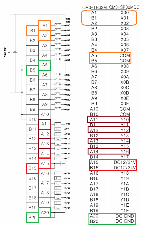
On the right-hand mapping, A1 is a physical position paired with X00; A11 is paired with Y10. The diagram also marks positions such as A5/B5 as COM, A15/B15 as DC12/24V, and A20/B20 as DC GND. These are not all interchangeable “spare I/O points”: some provide connections needed by the module or its input/output circuits. Their exact use must be checked against the hardware documentation before wiring.
The terminal block pictured here is part of this equipment’s PLC connection arrangement. A separate strip where incoming field cables land, such as the hypothetical TB1 used below, would be an additional set of terminals; it is not shown in this image.
Watch how Upmation finds module terminals on a drawing and then follows a pushbutton input and lamp output. The video uses different equipment from the image above, so follow the method, not its terminal numbers.
How to Read PLC Wiring Diagram | PLC Wiring Tutorial for Beginners | PLC Panel Wiring Diagram
In “How to Read PLC Wiring Diagram,” Upmation shows how module connection numbers and field-device signals appear in a larger drawing set.
Watch module terminals for the difference between a module’s channel and its numbered connection points. Then watch a pushbutton input, paying attention to the cable core and terminal strip between the button and input module. Finish with a lamp output to see the opposite signal direction. Do not assume that pressing a button must light a lamp in every project; that behavior depends on the PLC program.
Build a trace from the list to the wires
Here is a hypothetical small-panel example, separate from either pictured project. Assume its approved drawings and hardware instructions specify a suitable 24 V DC input circuit and a compatible sourcing output for the lamp. The I/O list has been extended with proposed connection details:
| Device and function | I/O-list entry | PLC connection | Proposed field-strip landing |
|---|---|---|---|
| PB-101, Start request | DI; normally open dry contact; 24 V DC sensing circuit | X00 at physical position A1 | PB-101 signal conductor at TB1:2 |
| PL-101, Running indication | DO; 24 V DC lamp | Y10 at physical position A11 | Lamp supply conductor at TB1:3 |
The X00/A1 and Y10/A11 pairings come from the pictured equipment pinout. PB-101, PL-101, and all TB1 positions are invented for this worked example; the image does not show those devices or field-strip landings.
To trace PB-101, begin with the function in its I/O-list row: the PLC is meant to detect a Start request. On the hypothetical wiring drawing, follow the panel’s 24 V sensing supply out through one field-strip position to the pushbutton contact. Follow its switched conductor back through TB1:2 to physical position A1, which the equipment pinout identifies as X00. Check the required input COM connection and return against the module instructions. With the assumed normally open contact, pressing the button completes the specified sensing circuit and makes the input active. The row and wiring tell you what the PLC can observe; they do not, by themselves, tell you what the program will do with that observation.
Now trace PL-101 in the other direction. The I/O row says the PLC issues a lamp command through Y10, available at A11 on this example hardware. On our hypothetical drawing, its conductor runs through TB1:3 toward the lamp; the lamp also needs a correctly specified return path. Do not copy that connection to an arbitrary output module. Whether an output sources voltage, sinks current, or uses a relay contact changes how its supply, load, and return must be wired. The I/O row identifies the intended load; the module documentation and wiring drawing establish the safe, complete circuit. An output command alone also does not prove that the lamp actually lit.
What turns those hypothetical TB1 references into build instructions? The panel documentation needs to associate them with cable cores, wire identifiers, and destinations. Blitzpanel describes this addition to an initial I/O list in the passage just after its tank-system example.
How To Make an I/O List for Your Control Panel Project | Blitzpanel
Return to Blitzpanel to see how an initial signal list gains the identifiers needed by a panel shop.
After “What You Can Learn From an I/O List - Real Example,” find the passage beginning “As an added note”; it comes before “Make Your Own I/O List - Final Summary.” Read from the shop additions. Focus on cable tags, wire numbers, conductor counts, and location: each helps someone follow an I/O row to a physical connection.
The same reasoning applies to analog signals, but the connection details change. If a row says PT-101, pressure, AI, 4–20 mA, look for the transmitter, its cable and field terminals, and an analog input channel compatible with that signal. The drawing and device specifications must settle such details as transmitter power, signal polarity, and the module’s return or common connection. You cannot assign PT-101 to X00 merely because X00 is unused: in the pictured pinout, X00 is a digital input. An AO row has the reverse direction: a varying command leaves an appropriate analog output channel for a compatible receiving device.
What to check when documents disagree
A reliable trace connects meaning to metal. For each I/O row, first establish the device tag, description, direction, and electrical signal. Then locate its module channel and physical connection, follow any wire or cable identifiers, and confirm where the field conductors land. Finally, look for the supply, common, and return required by that particular circuit.
If the I/O list says “level switch high” but the drawing labels the connected device “pressure switch,” or if two rows appear to claim the same channel, you have found a documentation discrepancy—not a reason to silently choose one. Record it and check the approved project information. Similarly, a blank terminal or missing return on the page you are reading may continue on another sheet; follow the references before concluding that the circuit is incomplete.
This tracing can be practised entirely from drawings. Work on a real energized panel, including measurements or wire changes, requires authorization and the appropriate isolation and safety procedures.
Conclusion
An I/O list tells you what each signal means and what electrical form it takes. A module pinout links a PLC channel to a physical connection, while wiring drawings and terminal information link that connection to cables and field devices. Keeping those identifiers distinct lets you follow an input into the controller or an output out to its load without mistaking a signal name for a terminal number—or a command for proof of operation.
Next, you will compare CAD tools used to turn information like this into maintainable electrical drawings.