Recommended resources
The freely available resources this lesson will direct you to.
- AutoCAD Vs AutoCAD Electrical !! Why Every Electrical Engineer should learn AutoCAD Electrical !!!www.youtube.com
- Draw Electronics Circuits the FREE and EASY way with TinyCAD - Part 1 - Introductionwww.youtube.com
- Electrical Toolset in Autodesk AutoCAD | Featureswww.autodesk.com
- Electrical Schematic Drawing Software: Free vs Paid Toolsiqelectro.com
Hello again. Last lesson, you followed an I/O-list entry from a field device through its terminals to a PLC channel. Today the question changes: what should you use to draw and maintain those connections?
A drawing can look correct while its wire numbers, device tags, and parts list disagree. We will compare standard AutoCAD, the AutoCAD Electrical toolset, and two lightweight alternatives by looking at how each handles that problem. This will help you choose a useful practice route before the course moves into drafting and electrical schematics. Allow about 35–40 minutes for the lesson and its resources.
The difference is what the software knows
Consider the hypothetical PB-101 Start pushbutton and PL-101 Running lamp from the previous lesson. In a general-purpose drafting program, you can draw a pushbutton symbol, a lamp symbol, and lines between them. You decide what those shapes mean, type their labels, and keep the labels consistent when the drawing changes.
Electrical-design software can store more than the appearance. Depending on the tool and how you set up the project, a symbol may carry a component tag and other properties; a conductor may have a managed number; related devices may have cross-references. That information can support updates and reports. It does not remove the need to check the circuit: an automatically numbered wire can still connect the wrong things.
This distinction is more useful than asking whether a program has electrical symbols. A collection of symbol pictures speeds up drawing. Electrical-aware features help maintain relationships among drawings and the information on them.
Standard AutoCAD and the Electrical toolset
Standard AutoCAD is a general CAD environment. For this course, its value is precise 2D drafting: placing geometry, editing it, organizing it on layers, and producing readable drawings. You could use it to draft a panel layout or a control schematic, including your own blocks for components. But a line drawn as a wire is not, merely by being a line, part of an electrical wire-numbering system. If you change a device tag or add a wire, you need a deliberate way to check the affected labels and documents.
AutoCAD Electrical adds a specialized electrical toolset to that drafting foundation. Autodesk describes symbol libraries, automated wire numbering and component tagging, project management, coil/contact cross-referencing, reports, and tools for PLC I/O drawings. Watch a short demonstration of two of those capabilities before reading the feature descriptions.
AutoCAD Vs AutoCAD Electrical !! Why Every Electrical Engineer should learn AutoCAD Electrical !!!
Edverciity LiveTechSkills’ “AutoCAD Vs AutoCAD Electrical” shows why PLC symbols and wire numbering matter to a controls drawing.
Watch PLC and wires: the presenter discusses PLC I/O library choices followed by automatic wire labeling. Focus on the kind of manual work these features can reduce, rather than treating the presenter’s speed or scale claims as a guarantee for every project.
Now read Autodesk’s description for a firmer account of what the toolset offers. It is a product page, so treat productivity claims as promotional; the feature descriptions are what matter here.
Electrical Toolset in Autodesk AutoCAD | Features
Read Autodesk’s “Electrical Toolset in Autodesk AutoCAD” to see which functions go beyond general drafting, especially those related to the I/O and device information you traced last lesson.
Start with the three capability statements near the top of the page, immediately before “Electrical toolset features.” Then, under “Discover specialised tools for electrical design,” read from “65,000+ electrical symbols” through “Coil and contact cross-referencing”: electrical features. Continue to “PLC I/O drawings from spreadsheets”; read the opening and finish that paragraph to see what input data the feature accepts. Pay particular attention to project management, wire and tag numbering, cross-references, and reports.
The PLC I/O symbol picker below makes the library idea concrete. It shows module and I/O-point choices, but it does not establish how a particular PLC must be wired.
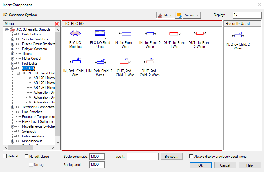
There is a practical trade-off. Electrical-aware features become most useful when the project’s symbols, wires, and component data are entered consistently. Merely opening an ordinary drawing in the Electrical toolset does not guarantee that every line and block has acquired those relationships. The toolset can assist with documentation, but it cannot independently verify that your I/O list reflects the machine’s intended behavior or that a module is wired according to its manual.
Two lighter routes: electrical schematics or general drafting
If access to AutoCAD is uncertain, distinguish between two different reasons to choose a lightweight tool.
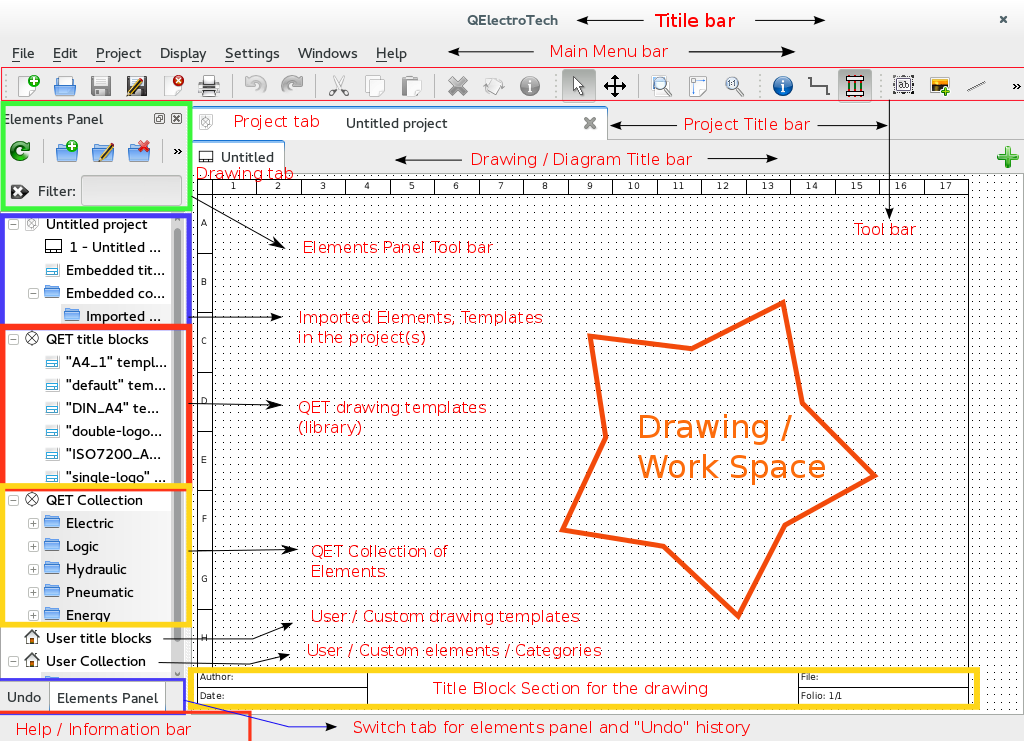
QElectroTech is aimed at electrical diagrams. It provides an element collection and project-oriented drawing workspace, with features described in the reading below for cross-references, conductor numbering, and exporting element data. That makes it a plausible place to practise building and revising small control schematics, rather than only arranging symbol pictures.
LibreCAD, in contrast, is a general 2D drafting alternative. It is useful for practising geometry, layers, and drawing organization. If you use it to make an electrical schematic, you must manage the electrical meaning—such as matching wire labels across sheets and keeping a parts list current—yourself.
Read this comparison for the distinction, but do not rely on a third-party comparison article as the final word on file-format compatibility or the features of a particular installed version.
Electrical Schematic Drawing Software: Free vs Paid Tools
Read the section “What free electrical schematic drawing software actually does now” for its contrast between QElectroTech’s electrical features and LibreCAD’s general drafting role.
In that section, read QElectroTech overview, then LibreCAD contrast. Focus on cross-references, numbering, and element data—not the article’s file-format claims, which should be checked against the software version you actually use.
These alternatives need not be identical substitutes for AutoCAD Electrical. A drawing that looks similar on screen may contain different underlying information in each application. Before depending on file exchange with a workplace, check which formats both specific installations can import or export and whether the electrical properties survive—not just whether the geometry appears.
Compare them against one realistic change
Suppose a small panel drawing already shows PB-101 connected to a PLC input, and PL-101 connected to an output. You are asked to add a second indication lamp and then issue revised drawings. The work is not just placing another circle on a sheet. You must keep its device tag, output assignment, wire labels, and any related documentation consistent.
| Tool | What helps you make the drawing | What needs particular attention when revising it |
|---|---|---|
| Standard AutoCAD | Precise 2D drafting and reusable drawing blocks | You maintain electrical tags, wire numbers, cross-references, and parts information through your own process. |
| AutoCAD Electrical | General drafting plus electrical symbols and project-oriented automation | Enter and maintain the right component and wire data; review generated numbering, references, and reports against the design. |
| QElectroTech | Electrical elements and selected numbering, reference, and data-export features | Check how your chosen project setup handles each feature and whether its outputs meet the drawing-package requirements. |
| LibreCAD | Lightweight general 2D drafting | Treat electrical consistency as a manual documentation task, not a built-in check. |
The choice depends on what you intend to practise. If today’s aim is to place and edit geometry accurately, general 2D CAD is enough. If the aim is to revise a multi-sheet control schematic without losing track of device and wire identities, electrical-aware software is more directly suited to the task. For professional delivery, the employer’s drawing standards, required file formats, licenses, and review process also matter.
For this course, a workable route is:
- Learn precise 2D drafting in AutoCAD if you have access to it; otherwise, use an available general 2D tool to practise the underlying drawing habits.
- Practise electrical schematics in AutoCAD Electrical when available, or use QElectroTech to work with electrical elements and project information.
- Keep the design information separate and clear—for example, an I/O list and agreed device tags—so that moving to a different tool does not require reinventing what the circuit means.
That is a learning route, not a promise of effortless conversion between applications. Software can transfer drawing geometry without preserving every electrical relationship.
Conclusion
Standard AutoCAD and LibreCAD help you draft; AutoCAD Electrical and QElectroTech add differing degrees of support for maintaining electrical information. For a small one-off drawing, manual coordination may be manageable. As drawings, devices, and revisions accumulate, numbering, cross-references, and report features become more consequential—but every output still needs engineering review.
Next, you will check what your available computer and access arrangements can actually support, including CAD and TIA Portal, and select a practical environment for the work ahead.