Hello! Welcome back to our vertical lift project.
In our last lesson, you did an excellent job of translating our system requirements into a concrete component specification. We provisionally selected a rolled ball screw with a 15 mm nominal diameter and a 10 mm lead.
This lesson continues directly from there. A ball screw excels at handling axial loads (pushing and pulling), but it isn't designed to support the weight of the payload or resist moments. For that, we need a dedicated guidance system. Today's learning outcome is to select and model standard guide rails and bearing blocks based on system requirements.
Our work will be divided into three parts, mimicking a real engineering workflow:
- Final Validation: We'll perform a critical speed check on the ball screw we selected last time, ensuring it's safe for our application.
- Selection: We'll analyze the forces acting on our system and use manufacturer data to select an appropriate linear guide size.
- Modeling: We'll bring our design into the virtual world by importing and mating the guide components in OnShape.
1. Final Validation of the Ball Screw
Before we move on, let's complete a crucial validation step we previewed in the last lesson: the critical speed check.
Critical speed is the rotational speed at which a long, spinning shaft becomes dynamically unstable and starts to vibrate or "whip." Operating near this speed can lead to excessive vibration, noise, and even catastrophic failure.
The formula for critical speed (n) is:
Where:
nis the critical speed in RPM.d_ris the root diameter of the screw shaft in mm. For our 15 mm nominal diameter screw, a typicald_ris about 12.5 mm.Lis the unsupported length between the support bearings in mm. We'll use our stroke length of 600 mm.fis a coefficient for the bearing support method. A common and robust configuration is "Fixed-Supported," for whichf = 1.5.
Let's calculate the critical speed for our screw:
Our required operating speed is 360 RPM. Since 360 RPM is well below the calculated critical speed of 520 RPM (we are operating at about 70% of critical speed), our 15 mm diameter selection is acceptable. For a greater margin of safety in a real-world design, we might consider a slightly larger diameter or a different support method if the operating speed were closer to the critical speed.
2. Selecting the Linear Guides
With the ball screw validated, we can now design the support system. We will use linear guide rails with recirculating ball bearing blocks.
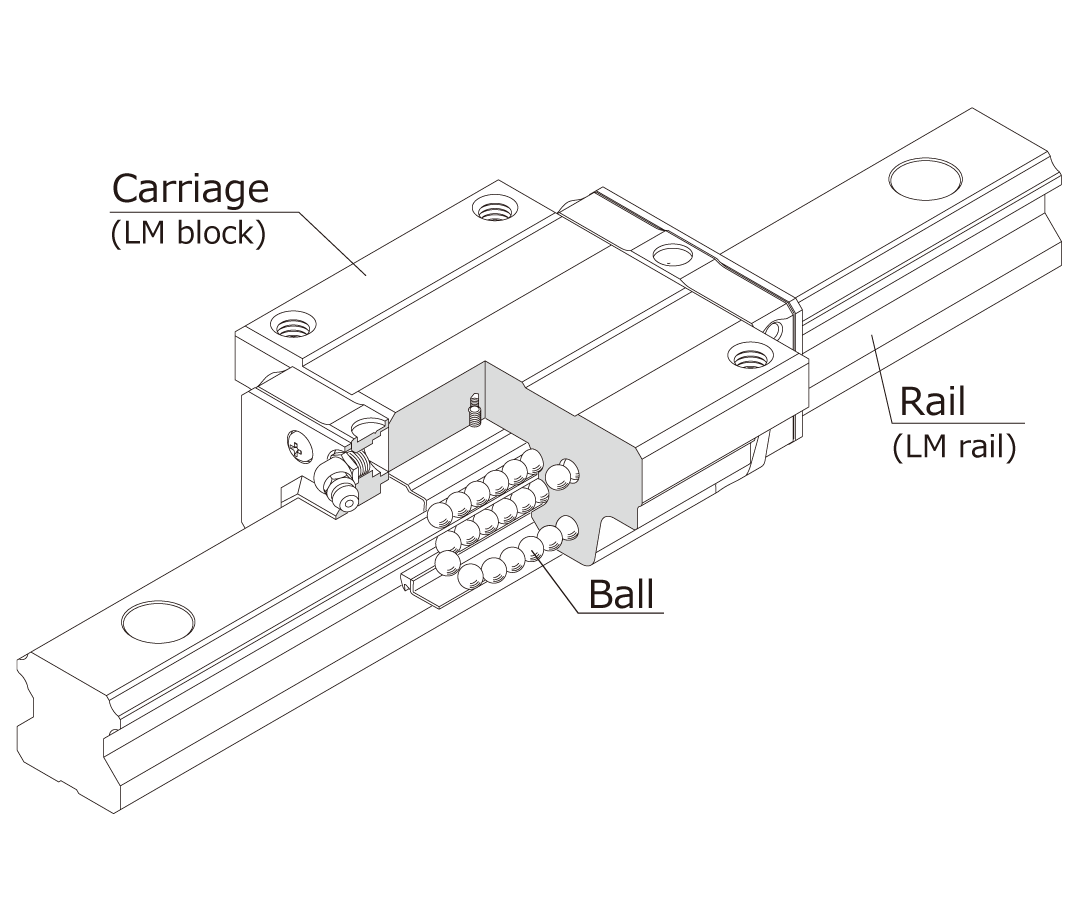
The selection process involves analyzing the loads on the blocks and ensuring they have a sufficient static load capacity.
Understanding the Loads
For our vertical lift, the 15 kg toolbox will be mounted on a platform that sits on the bearing blocks. Let's assume the center of gravity of the toolbox is offset from the plane of the guides. This offset creates a moment load, which is often the most significant load on the guides.
To provide stability, we'll use a standard configuration: two parallel rails, with two bearing blocks on each rail (four blocks total).
Let's define our layout:
- Distance between rails (
l_0): 250 mm - Distance between blocks on a single rail (
l_1): 150 mm - Load: 15 kg (~147 N)
- Load offset (distance from platform face to CoG,
l_x): 100 mm
This offset creates a pitching moment:
This moment is resisted by upward and downward forces on the front and back pairs of blocks. The force on each of the two blocks in the front (or back) pair due to the moment is:
The static weight is distributed among all four blocks:
The highest load occurs on the blocks that are supporting both the weight and the moment reaction.
This maximum calculated load on a single block is very small.
Applying a Static Safety Factor
Now we check this against a catalog. The most important initial check is the static load capacity, C_0. We must ensure we have an adequate static safety factor (f_s).
Linear Guide Selection Calculation | Ultimate Guide
This video from Master Mechanical DESIGN explains the selection process in detail. It introduces key concepts like static safety factor and demonstrates how engineers use online tools for these calculations.
Please watch from 01:19 to 02:52 to understand the concept of static safety factors for different applications. Then, watch from 06:32 to 15:32. Pay attention to how the loads are defined and how the Hiwin online tool is used to simplify the complex calculations. This demonstrates a very common industry practice.
As the video explains, manufacturers recommend safety factors based on the application. For a general industrial application with potential for light vibration, a safety factor (f_s) of 3 to 5 is appropriate. This means our selected block's C_0 should be 3 to 5 times our calculated maximum load P_max.
Required C_0 = P_max × f_s = 85.75 N × 5 = 428.75 N
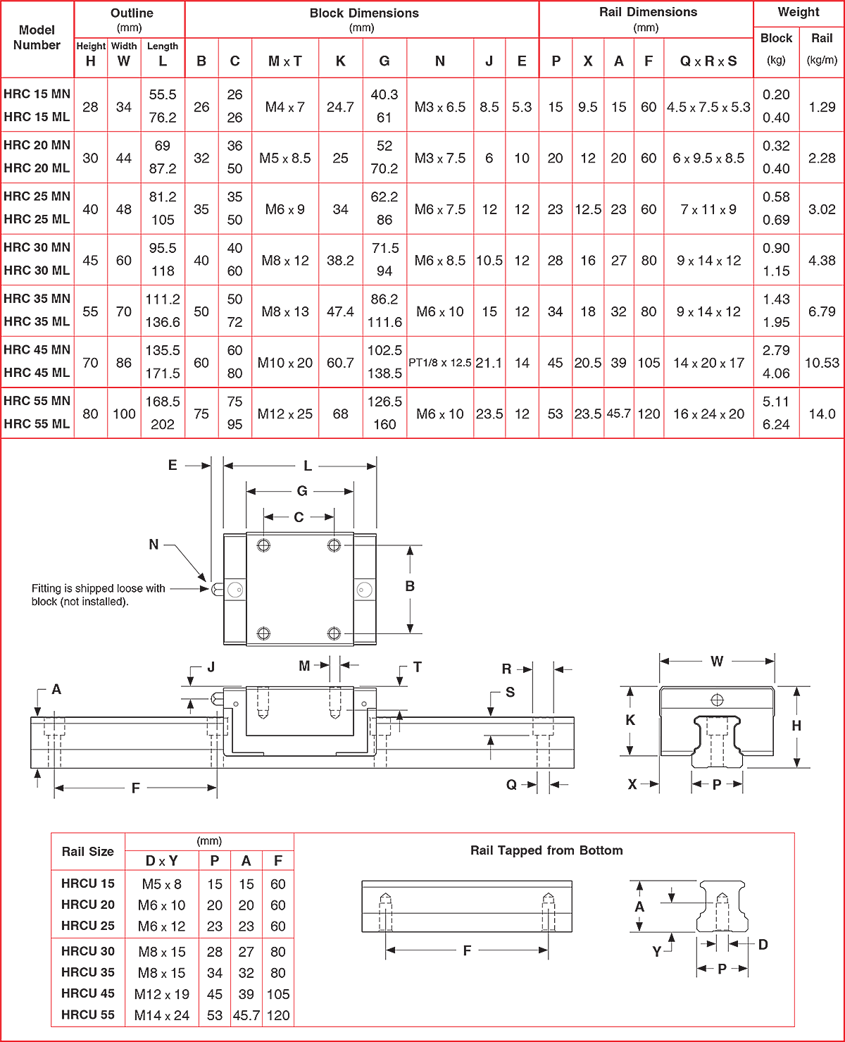
This required static capacity is extremely low. If we look at the datasheet for even the smallest standard size, like a 15 mm rail (e.g., HRC 15 in the image LINK), the static load capacity is typically in the thousands or tens of thousands of Newtons. For example, a standard size 20 block might have a C_0 of over 20,000 N.
This tells us that for this specific application, the load is not the driving factor. Instead, the choice of size will be driven by factors like general robustness, availability, and the size of fasteners needed for assembly. We will select a Size 20 linear guide (e.g., HRC 20, or a standard Hiwin HG/EG series). This is a very common size that provides good rigidity.
Our safety factor with a size 20 block would be enormous (f_s = 20000 / 85.75 > 200), so it is more than adequate.
For a deeper dive into the manual formulas, you can review this document from Rockford Ball Screw. It shows the full complexity of the calculations we approximated.
This guide provides the detailed equations for calculating loads on each block in various configurations. It is a good reference for understanding the underlying mechanics.
Skim through the document, paying particular attention to the 'Design Considerations' (Section A) and the diagrams showing load calculations for different orientations (pages 2-3). You don't need to perform the calculations, but notice how they account for static loads, acceleration forces, and moments to find the load on each block.
3. Modeling the Linear Guides in OnShape
Now that we've selected a Size 20 linear guide system, let's model it. As an engineer, you'll almost never model standard components like these from scratch. You'll download them from a supplier or a content library.
A great resource for this is McMaster-Carr. You can search for the component, configure it, and download a STEP file, which is a universal 3D CAD format.
Your Task:
- Go to the McMaster-Carr website (
www.mcmaster.com). - Search for "Linear Guide Rails and Carriages".
- Find a standard (e.g., Hiwin compatible) system. Select a 20 mm Rail Size.
- Download the STEP file for one rail (choose a length > 600 mm) and one carriage (block).
- In your OnShape project document, use the
+menu and selectImportto bring these two STEP files in.
Once imported, create a new Assembly tab. Now, we'll mate them.
How assembly mates work in Onshape
OnShape uses a powerful system of 'Mate Connectors' to define relationships between parts. This video gives a great overview of the different mate types.
Watch the section from 02:30 to 05:31. Focus on the explanation of the Slider Mate. This is precisely the mate we need for our application.
As you saw, the Slider Mate constrains 5 of the 6 degrees of freedom, leaving only translation along a single axis.
Let's assemble the first rail and block:
- Insert the rail and block into your assembly.
- Right-click the rail and select Fix. This locks your base component in space.
- Select the Slider Mate tool from the toolbar.
- Define the first mate connector: Move your cursor over the end face of the rail. OnShape will offer several potential points. Choose the point at the center of the rail's profile.
- Define the second mate connector: Move your cursor over the block. Choose a corresponding point, for example, the center of the opening where the rail goes through.
- Click the green checkmark to accept the mate.
- Now, try dragging the block with your mouse. It should slide smoothly along the rail but be unable to move in any other direction.
Test your understanding!
You applied a Slider Mate. Which degrees of freedom did this mate remove, and which one did it leave free? (Hint: The 6 DOFs are 3 translational (X, Y, Z) and 3 rotational (Roll, Pitch, Yaw)).
Show answer
The Slider Mate leaves one degree of freedom free: translation along the mate's Z-axis. It constrains or removes the other five: two translations (X and Y) and all three rotations (Roll, Pitch, and Yaw).
Conclusion
Fantastic work today. You've successfully navigated a complete component selection and modeling workflow, moving from high-level requirements to a functional CAD assembly.
Key Takeaways:
- You validated our ball screw selection by performing a critical speed check.
- You learned that for linear guides, moment loads are often the critical design driver.
- You followed an engineering process to select a guide size: analyze loads, apply a static safety factor (
f_s), and consult manufacturer ratings (C_0). - You sourced a standard component CAD model and used the Slider Mate in OnShape to create a realistic linear motion assembly.
Preview of the Next Lesson:
We now have our two key motion components specified: the ball screw and the linear guides. The next step is to model the ball screw assembly itself in OnShape and prepare to integrate it into our larger system. We will explore how to represent the screw, nut, and bearing supports in our CAD model.