Hello! Welcome back to our vertical lift project.
In the last lesson, we selected and modeled the size 20 linear guide system that will support our payload. With the guidance system in place, it's time to focus on the component that will actually drive the motion: the ball screw.
Today's learning outcome is to model the selected lead screw or ball screw assembly in OnShape. We'll tackle this by simulating a real-world engineering process, combining the use of standard parts with fundamental CAD modeling skills.
A Note on Modeling: Real-World Practice vs. CAD Skills
In an industrial setting, you would almost never model the complex internal workings of a standard component like a ball screw. The tiny recirculating balls and intricate raceways are computationally heavy and irrelevant for system-level integration. Instead, you would download a simplified 3D model from the manufacturer, just as we did for the linear guides.
However, knowing how to create custom screw threads from scratch is a fundamental CAD skill. It's essential for designing non-standard parts, custom adjustment screws, or even just representing threads accurately for visualization.
In this lesson, we will do both:
- Integrate a Standard Part: We will follow the industry-standard workflow by sourcing and assembling a simplified model of our selected ball screw.
- Build a Core Skill: We will then step aside from our main project to practice modeling a basic lead screw from scratch, using Onshape's
HelixandSweeptools. - Simulate the Motion: Finally, we'll learn how to make the parts move correctly in an assembly using a
Screw Relation.
1. Sourcing and Assembling a Standard Ball Screw
Our project requires a 15 mm diameter, 10 mm lead ball screw. The assembly consists of the screw shaft itself, the ball nut that travels along it, and the end support bearings that hold the screw in place and manage the axial loads.
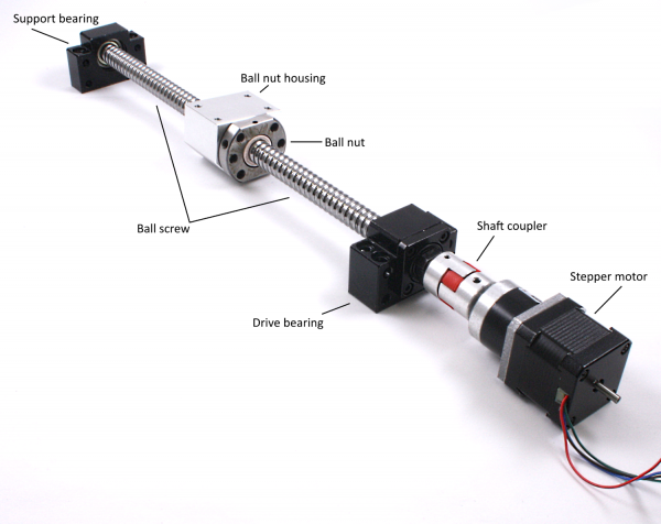
Just as with the linear guides, our first step is to source these components.
Your Task (Part 1):
- Navigate to a supplier website that offers CAD models, such as McMaster-Carr, Misumi, or a manufacturer site like THK.
- Search for a "Ball Screw Assembly".
- Configure a set of components that match our specifications:
- Ball Screw: ~15 mm diameter, 10 mm lead, length > 600mm.
- Ball Nut: Matching the 15 mm screw.
- End Supports: A set of fixed and simple supports for a 15 mm screw (often designated as BK/BF or FK/FF type supports).
- Download the STEP files for the screw, nut, and both end supports.
- In your Onshape project document, use the
+menu and selectImportto bring these components into your workspace.
Once imported, you will have a Part Studio for each component. For now, just confirm they are in your document. We will assemble them after learning about the specific mates required.
2. Modeling a Lead Screw from Scratch
Now, let's build a core CAD skill. We'll create a new Part Studio to model a simplified lead screw and nut. This will give you hands-on practice with the Helix and Sweep features, which are powerful tools for creating any kind of complex, path-based geometry.

The process involves creating a helical path and then "sweeping" a 2D profile along that path to create the 3D thread.
Onshape Lead Screw: A Comprehensive Guide
This guide provides an excellent step-by-step breakdown of how to model a lead screw in Onshape. We will follow this process closely.
Please read the section 'Designing Your Lead Screw in Onshape: Step-by-Step'. Focus on Steps 1, 2, and 3, paying close attention to the 'Using the “Helix” and “Sweep” Features' method. This outlines the exact workflow for creating threads.
To see this process in action, the following video provides a concise demonstration.
Learn Onshape: Drawing Threads for a Nut & Bolt
This video shows the practical application of the Helix and Sweep tools to create threads on both a bolt and a nut.
Watch from the beginning (00:00) to 03:41. Notice how the 'Pitch' of the helix is defined and how the 2D sketch of the thread profile is created and constrained to the start of the helix path.
Your Task (Part 2):
In a new Part Studio, try to replicate the process shown in the resources:
- Create a cylindrical shaft.
- Use the
Helixtool on one of the circular faces. Set the definition to Pitch and enter a value (e.g., 2 mm). - Create a new
Sketchon a plane that intersects the start point of the helix (e.g., the Front or Right plane). - Draw a small triangle or trapezoid for the thread profile. A key trick is to ensure the base of your profile is slightly smaller than the pitch to avoid errors.
- Use a
Coincidentconstraint to lock a point on your profile sketch to the end of the helix curve. - Use the
Sweeptool, selecting your profile sketch as the 'Face' and the helix curve as the 'Sweep path'.
This exercise is purely for skill development, but it's a valuable one. Your experience with parametric modeling in other software will serve you well here.
Test your understanding!
When creating a Helix for a functional screw, why is it better to define it by Pitch rather than by Turns?
Show answer
Pitch defines the linear distance the screw travels in one revolution. This is a fundamental mechanical property of the screw that needs to be constant. If you define it by Turns, the pitch would change every time you altered the length of the screw shaft, which is incorrect for a standard screw.
3. Assembling and Simulating Screw Motion
Now, let's return to our downloaded ball screw components and assemble them. We need to create a relationship where rotating the screw causes the nut to translate linearly. This is achieved by combining a Cylindrical Mate with a Screw Relation.
First, let's understand what a Screw Relation does.
Tech Tip: How to Use the Screw Mate Relation Tool in Onshape
This official Onshape Tech Tip gives a high-level overview of Mate Relations, focusing on the Screw Relation. It explains how it connects the rotational and translational degrees of freedom of another mate.
Read this short article. The key takeaway is that a Screw Relation isn't a mate itself; it's a behavior you apply to an existing mate (specifically, a Cylindrical Mate). Note the main input required: 'distance per revolution'.
The process is to first allow both sliding and rotation, and then link them together. The following video demonstrates this sequence perfectly.
Learn Onshape: Drawing Threads for a Nut & Bolt
The final section of the thread modeling video shows exactly how to apply a Cylindrical Mate and then add a Screw Relation to create realistic motion.
Watch from 05:44 to 08:35. Observe how a Cylindrical Mate is first applied between the nut and bolt. Then, the Screw Relation tool is used on that mate, and the 'distance per revolution' is set to match the screw's pitch.
Your Task (Part 3):
- Create a new Assembly tab in your Onshape document.
- Insert the ball screw, ball nut, and end support components you downloaded.
- Right-click the main screw shaft and select Fix. This will be our stationary reference. (In the final machine, one of the end supports would be fixed to the frame, but for now, this is simpler).
- Select the Cylindrical Mate tool. Create a mate between the outer surface of the screw shaft and the inner cylindrical surface of the ball nut. At this point, you should be able to drag the nut up and down and also rotate it freely.
- Now, select the Screw Relation tool from the toolbar.
- In the dialog box, select the
Cylindrical Mateyou just created. - For Distance per revolution, enter 10 mm. This is the lead of our selected ball screw.
- Click the green checkmark.
Now, try dragging the nut. You'll see that it rotates as it moves. Alternatively, right-click the nut and select "Animate." You should see the correct screw motion.
Conclusion
Excellent work. You've successfully modeled a critical assembly and learned how to simulate its unique motion, all while distinguishing between practical workflows and foundational skill-building.
Key Takeaways:
- For standard components like ball screws, the industry-standard workflow is to download and integrate supplier CAD models, not model them from scratch.
- Modeling custom threads is a valuable CAD skill accomplished using the
HelixandSweepfeatures. - To simulate screw motion in Onshape, you combine a
Cylindrical Mate(which allows rotation and translation) with aScrew Relationthat links them. - The key parameter for a
Screw Relationis the "Distance per revolution," which is equal to the screw's lead.
Preview of the Next Lesson:
We now have our primary motion components selected and modeled: the linear guides and the ball screw assembly. The next crucial step is to design the parts that connect everything. In the next lesson, you will design and model the custom mounting brackets needed to hold the motor and attach the ball screw assembly to our lift's structure. This is where we will start creating our own unique, project-specific parts.