Hello! Welcome back to our project on designing a vertical lifting system.
In our last lesson, we took the crucial first step of defining the system requirements. We translated the goal of lifting a 15 kg toolbox by 600 mm in 10 seconds into a clear set of engineering specifications. As a quick recap, our key requirements are:
- Load (Force): 300 N (including a 2.0x safety factor)
- Orientation: Vertical
- Speed: 60 mm/s
- Travel (Stroke): 600 mm
Today, we will use these requirements to achieve our next learning outcome: to perform sizing calculations for a lead screw or ball screw. This is where we move from abstract requirements to concrete hardware specifications. We'll select the core component that converts the motor's rotation into the linear motion that lifts the toolbox.
1. Lead Screws vs. Ball Screws: The Core Trade-off
The two most common choices for screw-driven linear motion are lead screws and ball screws. Your mechanical engineering background gives you a head start here, as the key difference lies in the type of friction they use.
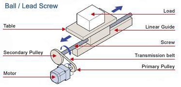
-
Lead Screws: These operate on the principle of sliding friction. The threads of the nut slide directly against the threads of the screw. A common, efficient profile for lead screw threads is the Acme thread.
- Pros: Lower cost, simple design, often self-locking (the load won't back-drive the screw if the lead angle is small enough), which is a benefit in vertical applications.
- Cons: Lower efficiency (typically 30-70%) due to high friction, which generates heat. This limits their speed and duty cycle. They also experience more wear.
-
Ball Screws: These use rolling friction. A series of ball bearings recirculate within the nut and roll in a helical raceway on the screw.
- Pros: Very high efficiency (typically >90%), allowing for higher speeds, heavier loads, and higher duty cycles with less motor power. They have a longer lifespan due to lower wear.
- Cons: Higher cost, more complex design, and they are not self-locking. For a vertical application like ours, a brake on the motor or an external brake is required to prevent the load from falling when power is off.
To get a better sense of these components, the following video explains the key terminology and the difference between the two main manufacturing methods: rolling (cost-effective) and grinding (high precision).
Ball Screw Selection Calculation Made Easy | Ultimate Guide 🔥
This video from Master Mechanical DESIGN provides a fantastic introduction to ball screw terminology and selection. It clarifies concepts like accuracy grades, rolled vs. ground screws, and lead vs. pitch.
Please watch the first section from the beginning until 06:22. Focus on the definitions of accuracy grade, rolled vs. ground screws, and the distinction between lead and pitch.
Decision for Project 1:
For our vertical lift, a lead screw could be a viable option due to its self-locking nature and lower cost. However, for modern automated systems where smooth motion and efficiency are valued, ball screws are often the preferred choice. Since our goal is to build a portfolio demonstrating contemporary design practices, we will proceed with sizing a rolled ball screw. They offer a great balance of performance and cost.
2. The Ball Screw Sizing Process
Selecting a ball screw is a systematic process that directly uses our requirements. Professional engineers follow a procedure very similar to this, often referencing manufacturer catalogs.
To see what this process looks like in a professional context, let's look at a selection guide from MISUMI, a major component supplier. It outlines the step-by-step procedure engineers follow.
Skim through the 'Selection Process' diagram and the 'Ball Screw Selection Procedure' table on pages 1-2 (PDF pages 1-2). This will give you a high-level map of the steps we're about to take: define conditions -> make a provisional selection -> check against constraints (load, speed, life).
Our sizing process will focus on three key parameters in this order:
- Accuracy Grade: Based on positioning needs.
- Lead: Based on speed requirements.
- Shaft Diameter: Based on load and length.
3. Sizing Calculations for Our Project
Let's apply this process to our vertical lift requirements. We'll use the THK selection example as a guide for our calculations.
The 'Example Ball Screw Selections' document from THK provides worked examples of this entire process. We will follow a similar logic for our own project.
Review the 'Selection Conditions' and the first two steps: 'Selecting Lead Angle Accuracy and Axial Clearance' and 'Selecting a Screw Shaft' (which includes selecting the lead and diameter). Notice how the input conditions directly drive the calculations.
Step 1: Select Accuracy Grade
Our requirement for precision is very loose: +/- 5 mm. Ball screw accuracy is classified into grades (e.g., C0, C3, C5, C7, C10).
- Precision Ground (C0-C5): Used for high-precision applications like CNC machines or metrology equipment. Very expensive.
- Rolled (C7-C10): Used for transport and general automation applications. Cost-effective.
Our +/- 5 mm requirement is easily met by the lowest accuracy grades. We will provisionally select a C7 grade rolled ball screw, which is a widely available and economical choice.
Step 2: Calculate and Select the Lead
The lead of a screw is the linear distance the nut travels for one full revolution of the screw. It connects the motor's rotational speed to the system's linear speed.
The formula is:
We know our desired linear speed is 60 mm/s. We need to make a reasonable assumption for the motor's rotational speed. As seen in the resources, a typical rated speed for an AC servo motor is 3000 RPM. Let's use this for our initial calculation.
A lead of 1.2 mm is not a standard size. Manufacturers offer a set of standard leads, such as 5 mm, 10 mm, 16 mm, 20 mm, etc. We must choose a standard lead and see how that affects our system.
Let's select a standard 10 mm lead. Now, we re-calculate the required motor speed to achieve our target linear speed:
This is a perfectly acceptable speed for a servo motor or even a stepper motor. It gives us flexibility in motor selection and potential gearing options later.
Provisional Selection: Lead = 10 mm.
Step 3: Determine the Screw Shaft Diameter
The shaft diameter must be large enough to withstand the applied loads without failing and to operate at the required speed without vibrating excessively. The primary load-based failure mode we must consider is buckling. Because our screw is in a vertical orientation, it will be under compression as it pushes the 15 kg load upwards, acting like a slender column.
We can use the Euler buckling formula, which is simplified in manufacturer catalogs for easy use. The allowable buckling load P is given by:
Where:
Pis the allowable axial load in Newtons. We needP> 300 N.d_ris the root diameter of the screw shaft in mm (the diameter at the bottom of the threads).Lis the unsupported length between the support bearings in mm. We can approximate this with our stroke length: 600 mm.mis a coefficient based on how the ends of the screw are supported. A common and robust configuration is Fixed-Supported, for whichm = 10.
We can now rearrange the formula to solve for the minimum required root diameter, d_r:
Plugging in our values (using our required force of 300 N for P):
This means we need a ball screw with a root diameter of at least 5.73 mm to be safe against buckling.
Now, we consult standard catalog sizes. Common nominal (outer) diameters are 15 mm, 16 mm, 20 mm, etc. A 15 mm nominal diameter ball screw typically has a root diameter of around 12.5 mm, which is well above our calculated minimum of 5.73 mm.
Therefore, a 15 mm diameter screw is more than strong enough to handle the buckling load.
Provisional Selection: Nominal Diameter = 15 mm.
Test your understanding!
Let's say the project requirements change, and the stroke length (L) must now be 1200 mm (a much longer lift). Using the same buckling formula and a required force of 300 N, what is the new minimum required root diameter d_r? How does this demonstrate the challenge of designing long, slender systems?
Show answer
By doubling the length, the minimum required root diameter increased from 5.73 mm to 8.11 mm. This shows that the required diameter is highly sensitive to the length of the screw (L^2 term in the numerator). For long-stroke applications, buckling and a related issue, critical speed (or "shaft whip"), often become the driving factors in selecting a much larger diameter screw than the load alone would suggest.
Step 4: A Brief Look at Torque
With your ME background, you'll recognize that the motor must provide enough torque to drive this system. For a highly efficient ball screw, the driving torque T can be approximated by:
Where F is the axial force (300 N), Lead is 10 mm (0.01 m), and η (eta) is the efficiency (approx. 0.9 for a ball screw).
This calculation gives us a rough estimate of the torque required from the motor, a topic we will explore in more detail when we select the motor.
Conclusion
Excellent work! You have successfully translated the system-level requirements into a concrete specification for a key mechanical component. This is a core task for any mechanical design engineer.
Key Takeaways:
- You've learned the fundamental differences and trade-offs between lead screws and ball screws.
- You followed a systematic sizing procedure: evaluating accuracy needs, then calculating lead from speed, and finally determining diameter from load.
- You performed a buckling calculation to ensure the screw's structural stability, a critical check for any component under compressive load.
- You have arrived at a provisional specification for our project's core component:
- Type: Rolled Ball Screw
- Accuracy: C7 Grade
- Nominal Diameter: 15 mm
- Lead: 10 mm
Preview of the Next Lesson:
A ball screw is designed to handle axial loads, not significant side loads or moments. To create a stable system, we need to add linear guides. In the next lesson, we will select and model standard guide rails and bearing blocks that will support the lifting platform. We will also perform a critical speed check on our 15 mm diameter screw to ensure it won't vibrate at our operating speed—a final validation of today's selection.