Hello! Welcome to your next lesson in the "Engineering Workflow and System Design" module.
In our last session, we focused on selecting the right type of mechanism—like a linkage or a cam—to produce a specific motion. Now, we'll address the crucial next question: once you've chosen the mechanism's form, what material should you use to build it? This decision is fundamental to a component's performance, cost, and reliability.
Today, you will learn to perform systematic material selection with trade-off analysis for a given application. This moves beyond simply picking a material you're familiar with and into a structured, data-driven process that is essential in a professional engineering workflow. This method allows you to justify your design choices with clear evidence, a key skill for your portfolio projects.
1. The Material Selection Framework
The world of engineering materials is vast, with thousands of options. To navigate this landscape effectively, engineers use a systematic approach. The most widely accepted method was pioneered by Professor Michael Ashby at Cambridge University.
This video provides an excellent overview of the different families of materials and introduces the four key steps of the Ashby method.
How Mechanical Engineers Select the Right Material
Watch this introduction from 'Engineering Gone Wild' to get a mental map of the material families and the systematic framework used in industry.
Please watch from the beginning to 06:47. Pay close attention to: The four main material families and their general characteristics (00:00 - 04:13). The four steps of the Ashby selection process: Translation, Screening, Ranking, and Validation (04:13 - 06:47).
As the video explained, the process can be summarized as:
- Translate: This is the most critical step. You must translate your design requirements (e.g., "the part must be lightweight and not bend") into precise engineering constraints and objectives (e.g., "minimize mass, subject to a maximum deflection").
- Screen: Use your constraints to eliminate materials that absolutely cannot do the job. For example, if a part operates at 300°C, most polymers are immediately screened out.
- Rank: For the materials that passed the screening, you now need to find which is "best." This is where we use performance indices and Ashby charts to rank the candidates based on how well they meet our objectives.
- Document & Validate: Investigate the top-ranked candidates in more detail, considering factors like cost, availability, and specific manufacturing requirements. This is where your knowledge of FMEA and manufacturing processes becomes invaluable.
2. Ashby Charts and Performance Indices
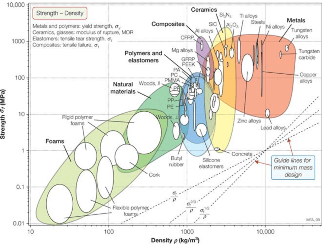
The power of the Ashby method comes from its quantitative approach to ranking. We combine material properties into a performance index—a single number that measures how well a material performs a specific function.
Let's walk through a concrete example. We want to design a bike frame that is both stiff and lightweight. How do we find the best material for this job?
The following video does an excellent job of deriving the performance index for this exact problem from first principles and showing how to use it with an Ashby chart. Given your background in mechanics, you'll find the derivation straightforward.
How to select materials using Ashby plots and performance indexes
This video by Dr. Billy Wu will guide you through deriving a performance index for a light, stiff beam and using it on an Ashby chart to select materials.
Please watch from 01:06 to 06:06. Focus on: How the mass and deflection equations for a simple beam are combined to isolate the material properties (01:06 - 04:11). How the resulting performance index, M = E^{1/2}/\rho, is represented as a line with a specific slope on a log-log plot (04:11 - 06:06).
As the video demonstrated, the goal is to maximize the performance index, . For a light and stiff beam, the index is:
Where:
- is the Young's Modulus (stiffness)
- is the density
On a log-log plot of Young's Modulus (y-axis) vs. Density (x-axis), materials with the same value of fall on a straight line with a slope of 2. To find the best materials, you move this line up and to the left until only a few candidates remain. Materials like CFRP, wood, and certain metal alloys rank highly for this specific application.
To help you put this process into practice, here is a clear, step-by-step recipe for deriving a performance index for any design problem.
MATERIALS SELECTION IN THE DESIGN PROCESS
These lecture notes provide a concise 'Recipe for Optimization' that formalizes the process of deriving a material performance index. This is a great reference to have for your projects.
Please read the section titled 'RECIPE FOR OPTIMIZATION' on page 16. It breaks the process down into 7 clear steps. You don't need to read the full document, just this recipe.
Test your understanding!
Using the "Recipe for Optimization," consider a different problem: designing a light, strong tie-rod (a bar loaded in pure tension).
- Function: A tie-rod of a given length must carry a tensile load without failing.
- Objective: Minimize mass, .
- Constraint: The stress in the rod, , must not exceed the material's failure strength, . Stress is , where is the cross-sectional area.
What is the material performance index that you would want to maximize for this application?
Show answer
- Objective function: We want to minimize mass, so we want to maximize performance . The mass is . So, .
- Constraint: The rod must not fail, so the stress must be less than the material's strength: . At the limit, we have .
- Eliminate the free variable: The free geometric variable is the area, . From the constraint, we can solve for it: .
- Substitute into the objective function:
- Identify the material index: The first term contains the functional requirements and geometry. The second term contains only material properties. Therefore, the material performance index to maximize is:
This is the specific strength, a very common performance index for lightweight, strength-limited designs.
3. Trade-Offs and Multiple Constraints
A real design is never optimized for a single objective. We are always balancing competing requirements, such as performance vs. cost. This is the "trade-off analysis" part of the learning outcome.
The bike frame example from the video already touched on this by adding cost as a secondary factor. Let's formalize this.
Method 1: Sequential Screening
The simplest method is to use your most important performance index to create a shortlist of candidates, and then use other criteria to rank that shortlist. A case study on selecting material for a spur gear illustrates this process well.
Material Selection for Spur Gear Design Using Ashby Chart
This paper demonstrates a practical application of the Ashby method for designing a spur gear. It shows how to screen for performance (strength/density) and then rank the results using cost.
Read sections 2 ('Material Selection Strategy'), 2.4 ('Screening'), and 2.5 ('Ranking'). Focus on how they first use a performance index to get a list of candidates (Table 1) and then use a cost chart to narrow down the selection.
Method 2: Active Constraint and Coupling Equations
A more rigorous approach is needed when you have multiple, equally important constraints. A design is only as good as its weakest link. The active constraint is the one that most limits the performance. You must design to satisfy this limiting constraint first.
For example, a part might need to be strong enough and stiff enough.
- The strength constraint gives you one performance index:
- The stiffness constraint gives you another:
You can calculate the performance for both and see which one is the limiting factor for each material. The document MATERIALS SELECTION IN THE DESIGN PROCESS explains this "active constraint" method (section 7) and a related "coupling equation" method (section 8). While we won't go deep into the math today, the key takeaway is that there are systematic ways to handle these overconstrained problems without resorting to guesswork.
The Importance of Manufacturing
Finally, a theoretically perfect material is useless if you can't make your part from it at a reasonable cost. The choice of material is intrinsically linked to the manufacturing process.
The first video we watched has an excellent segment that gives practical examples of these trade-offs.
How Mechanical Engineers Select the Right Material
Let's revisit 'How Mechanical Engineers Select the Right Material' to see some real-world examples of how manufacturing considerations can override purely performance-based selections.
Please watch from 06:47 to 10:11. Notice the discussion on why you can't easily weld 7075 aluminum, a classic trade-off between strength and manufacturability.
The comparison between 6061 and 7075 aluminum is a perfect example. While 7075 is nearly twice as strong, its poor weldability makes 6061 the default choice for many applications where welding is required. This is the kind of practical knowledge that distinguishes an experienced engineer.
Conclusion
You now have a powerful, systematic framework for making and justifying material selections. This process transforms a potentially overwhelming decision into a logical sequence of steps.
Key Takeaways:
- Systematic Approach: Use the Ashby method (Translate, Screen, Rank, Document) to structure your material selection process.
- Performance Indices: Quantify a material's suitability for a specific task by deriving a performance index from the governing physics of the problem.
- Ashby Charts: Use these log-log plots to visually compare thousands of materials and rank them according to your performance index.
- Trade-Offs are Key: Real-world selection always involves balancing multiple, often conflicting, objectives such as performance, cost, and manufacturability.
In our next lesson, we will continue building our system design skills by focusing on how to analyze and select appropriate fastener types for different loading conditions. Just as with materials, this is a decision that requires a systematic approach to ensure a safe and reliable design.