Hello! Welcome to your next lesson in the "Engineering Workflow and System Design" module.
In the previous lesson, we learned how to use the Kutzbach criterion to calculate a mechanism's degrees of freedom, or mobility. This is a critical first step to ensure a proposed design can move as intended. Now that we can verify if a mechanism will move, we'll focus on how to choose the right one to produce the specific motion we need.
Today's learning outcome is to select appropriate mechanism types (e.g., linkages, cams) for specific motion requirements. This is a core skill in mechanical design, moving us from abstract analysis to tangible concept selection. We will explore a variety of common mechanisms, categorizing them by the type of motion they create and examining the trade-offs involved in choosing one over another.
1. A Framework for Mechanism Selection
As an engineer, you don't choose a mechanism at random. The selection is driven by the design requirements. The most fundamental requirement is the desired motion conversion. We can broadly categorize mechanisms based on how they transform an input motion (typically from a motor) into a desired output motion.
The article "Understanding Mechanical Mechanisms" provides a helpful table that classifies mechanisms by their function.
Understanding Mechanical Mechanisms – Types and How They Work
This article from the MISUMI meviy blog provides a great overview of common mechanisms, categorized by the type of motion they produce. This is a very practical way to think about mechanism selection.
Please read the introduction and the first two sections, 'What Are Mechanical Mechanisms?' and 'Types of Mechanical Mechanisms,' including the table. Focus on how the table organizes mechanisms by their motion conversion type (e.g., Rotary to Linear, Rotary to Intermittent).
We will use this framework to explore some of the most important mechanism types.
2. Converting Rotary Motion to Linear Motion
This is one of the most common tasks in automation and machine design. Our first project in this course, a linear actuator, will require exactly this type of conversion.
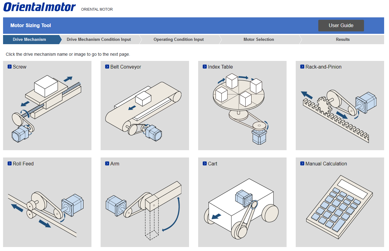
There are several standard ways to achieve this conversion, each with distinct advantages and disadvantages.
Understanding Mechanical Mechanisms – Types and How They Work
Let's return to the MISUMI article to see a direct comparison of the three most common rotary-to-linear mechanisms.
Read section '1. Converting Rotary Motion to Linear Motion' and study the comparison table for Ball Screw, Timing Belt, and Rack & Pinion. Pay close attention to the trade-offs in accuracy, speed, stroke length, and cost.
Summary of Rotary-to-Linear Mechanisms:
- Ball/Lead Screws: Excellent for high precision and generating large forces. Their main limitation is that for very long strokes, the screw can sag or experience critical speed issues (whipping). You'll perform sizing calculations for these in the next module.
- Timing Belts: Ideal for high speeds over long distances. They are quieter and cheaper than screws but can stretch under high acceleration, which reduces their positional accuracy.
- Rack & Pinion: Also good for long strokes and can handle high acceleration. They are mechanically simpler than a long belt system but can be noisy and require lubrication.
Another clever mechanism for this conversion is the Scotch Yoke, which produces pure sinusoidal linear motion. It's simpler than a traditional crank-slider but can have high contact stress and wear in the slot.
3. Converting Continuous Rotation to Intermittent or Complex Motion
Many industrial processes require a part to be moved into position, held stationary (a "dwell" period) for an operation, and then moved again. This requires converting a motor's continuous rotation into start-stop, or intermittent, motion. Other applications require a non-uniform or oscillating motion.
Cams and linkages are the classic solutions for these tasks. To get a feel for a variety of these mechanisms and their applications, let's watch the following video.
Mechanisms EVERY Mechanical Engineer Should Know
This video from 'Engineering Gone Wild' provides an excellent survey of fundamental mechanisms that every mechanical engineer should know. It covers their function, applications, and key design considerations.
Please watch the segments on the Cam (00:53-02:54), Geneva Mechanism (02:54-04:45), Four-Bar Linkage (07:03-08:26), and Scotch Yoke (08:14-09:32). As you watch, think about: What kind of motion does each mechanism produce? What is a typical industrial or automotive application for each?
Let's break down these key mechanisms:
Cams
A cam is a rotating or sliding component with a specifically shaped profile that imparts a desired motion to a follower.

- Function: Cams are the original form of "mechanical programming." They can create nearly any custom motion profile (linear, oscillating, intermittent) just by changing the shape of the cam.
- Key Advantage: Highly versatile and reliable for creating complex, repeatable motion paths with built-in dwell periods. The motion profile can be optimized to minimize jerk (the rate of change of acceleration), which is crucial for smooth, high-speed operation.
- Trade-offs: The complex profile can be expensive to manufacture. At high speeds, the follower can lose contact with the cam ("follower jump"), requiring careful design of the follower spring or using a groove cam.
Geneva Mechanism
This is a specialized mechanism for producing intermittent rotary motion from a continuous input.
- Function: A drive pin engages with slots on a driven wheel, causing it to rotate by a precise angle and then dwell while the pin disengages.
- Key Advantage: Simple, robust, and cost-effective for creating precise indexing motion (e.g., for an indexing turntable on an assembly line).
- Trade-offs: The engagement and disengagement can cause significant impact and jerk, making it less suitable for very high speeds or delicate applications compared to a well-designed cam.
Linkages
Linkages consist of rigid bodies (links) connected by joints (pivots). The four-bar linkage is the most fundamental and versatile type.
- Function: By changing the lengths of the four links, you can generate a wide variety of output motions, including oscillation, rotation, and complex coupler curves that can approximate straight lines or other paths.
- Key Advantage: Simple to construct, high reliability, and high load capacity. They are found everywhere, from automotive suspension systems (controlling wheel motion) to heavy construction equipment.
- Trade-offs: Synthesizing a linkage to produce a specific desired path can be complex. Their motion is fixed by the link lengths and cannot be easily changed like an electronic cam.
Test your understanding!
You are tasked with designing a small automated test rig. A component needs to be pushed linearly into place, held for two seconds while a sensor takes a measurement, and then retracted. The cycle needs to repeat every five seconds. The motion should be as smooth as possible to avoid vibrating the sensor.
Which mechanism type would be most suitable for this task: a ball screw, a four-bar linkage, or a cam? Justify your choice.
Show answer
A cam mechanism would be the most suitable choice. Here's why:
- Built-in Dwell: The core requirement is "push, hold (dwell), retract." A cam profile can be designed with a constant-radius section that corresponds to the two-second dwell period, holding the follower stationary while the cam continues to rotate at a constant speed.
- Smooth Motion: The cam profile can be designed using curves (like cycloidal or modified trapezoid profiles) that provide very smooth, controlled acceleration and deceleration, minimizing jerk and vibration.
- Why not the others?
- A ball screw is excellent for linear motion, but creating a two-second dwell would require stopping, holding, and reversing the drive motor. While possible with a servo motor, it's more complex from a controls perspective than the purely mechanical solution a cam offers.
- A standard four-bar linkage produces continuous motion. While some special linkage configurations can approximate a dwell, it's not as precise or easy to implement as a cam's dwell.
4. Mechanisms for Power Transmission
Sometimes the goal isn't to change the type of motion, but to transmit it from one place to another, often while changing its speed and torque. This is the domain of gears, belts, and chains.
Given your background, you're certainly familiar with these from automotive powertrains. The key in design selection is knowing the specific trade-offs.
How to Select Mechanisms for Motion Transmission
This article from Encata provides an excellent breakdown of when to choose one power transmission method over another. It includes a useful 'Signs you likely need...' section for each.
Please read the sections on 'Gear Drive', 'Belt Drive', and 'Chain Drive'. Focus on the strengths, limitations, and example applications for each.
While gears are a vast topic, it's useful to be familiar with the main types and their common applications.
Gear Types, Design Basics, Applications and More - Basics of Gears
The video 'Gear Types, Design Basics, Applications and More' gives a quick but comprehensive visual tour of different gear types and, crucially, shows them in real-world applications.
First, watch the overview of gear types from 00:46 to 04:02. Then, watch the application examples from 09:43 to 15:22. Note how specific gear types are chosen for specific jobs (e.g., helical gears for quiet operation in a car transmission, bevel gears for 90-degree power transmission in a differential).
Summary of Power Transmission Mechanisms:
- Gears:
- Use when: You need a compact, high-torque, slip-free power transmission with a precise speed ratio.
- Examples: Spur (simple, noisy), Helical (quieter, for parallel shafts), Bevel (for intersecting shafts, e.g., 90°), Worm (high reduction ratio, often self-locking).
- Belts:
- Use when: You need to transmit power over a larger distance, and you want quiet operation and some vibration damping. Not ideal for high-precision synchronized motion unless you use a timing belt.
- Chains:
- Use when: You need slip-free transmission over a large distance and at high loads where a belt might slip. They are more robust than belts in harsh environments but are noisier and require lubrication.
Conclusion
Selecting the right mechanism is a foundational skill that combines knowledge of kinematics with practical engineering trade-offs. It's about matching the unique characteristics of a mechanism to the specific motion requirements of your design problem.
Key Takeaways:
- Categorize by Motion: The first step in selection is identifying the required motion conversion (e.g., rotary to linear, continuous to intermittent).
- Rotary to Linear: Your main choices are screws (precision), belts (speed over distance), and rack & pinion (load over distance).
- Complex or Intermittent Motion: Cams offer unparalleled flexibility for custom motion profiles with built-in dwells. Geneva mechanisms are a simple solution for indexing. Linkages are robust and versatile for generating oscillating or complex paths.
- Power Transmission: The choice between gears, belts, and chains depends on trade-offs between speed, torque, distance, noise, precision, and cost.
In our next lesson, we will begin looking at systematic material selection. Once you've chosen a mechanism type like a four-bar linkage, you still need to decide what material to make the links from. This decision depends on factors like strength, stiffness, weight, and cost, which we will explore next.