Hello! In our last few lessons, we've performed targeted analyses on our rotary mechanism, examining bearing life and shaft deflection to ensure individual components meet their specific performance criteria. While these analyses are essential, a professional engineering workflow also requires a systematic, high-level assessment of the entire system to proactively identify potential risks.
Today, we will address this by conducting a Failure Mode and Effects Analysis (FMEA). The learning outcome for this lesson is to conduct an FMEA for the rotary mechanism, assessing failure modes and their effects.
Your experience with FMEA will be a great foundation. We'll build on it by focusing specifically on the Design FMEA (DFMEA), using an industry-standard, structured approach to identify how our design could fail and what the consequences would be. This process is a cornerstone of risk management in product development and a crucial skill for your portfolio.
1. What is a Design FMEA?
A Failure Mode and Effects Analysis (FMEA) is a systematic, proactive method for evaluating a design to identify, prioritize, and mitigate potential failures before they can occur. Instead of reacting to problems after they happen, we try to anticipate them.

There are different types of FMEA, but our focus is the Design FMEA (DFMEA), which analyzes the design of the product itself. This is distinct from a Process FMEA (PFMEA), which analyzes the manufacturing and assembly processes.
Booklet No. 14: Failure Mode and Effects Analysis (FMEA)
To get a formal understanding of the goals and benefits of FMEA in an industrial context, let's review a professional guide from Bosch, a major player in the automotive and engineering sectors.
Please read Chapter 1, 'Introduction' (pages 3-5). Focus on Section 1.1 'Aims' and Section 1.3 'Benefits'. This will solidify why this activity is so valuable in a real-world engineering environment.
As the guide highlights, the core benefits of a DFMEA include increasing product reliability, minimizing costly late-stage design changes, and building a comprehensive knowledge base about the product's risks.
2. The FMEA Process: A Step-by-Step Guide
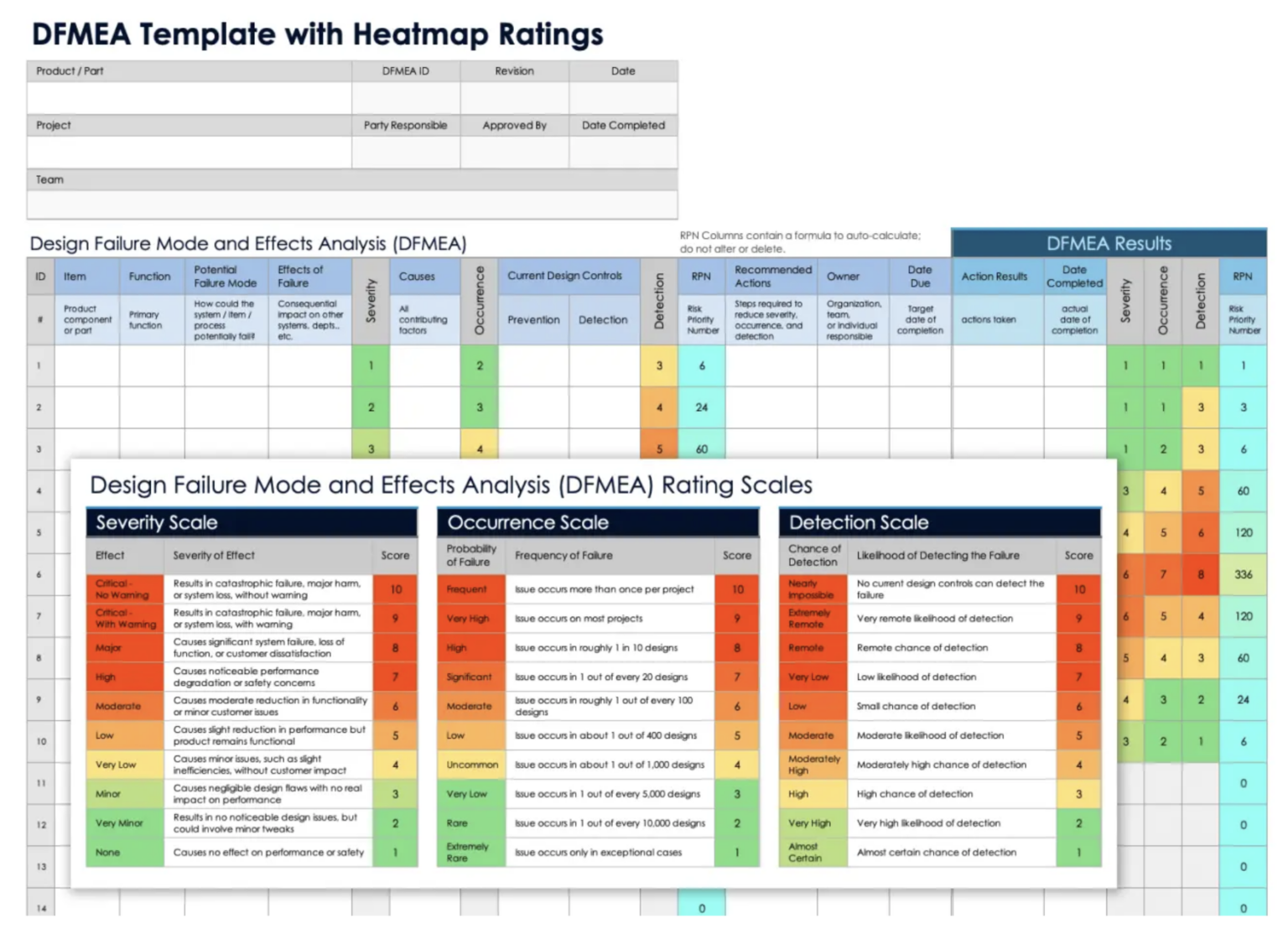
The FMEA process is captured in a standardized worksheet. We will walk through the key columns of this worksheet, which represent the logical steps of the analysis.
To understand how to fill out this template, we'll watch a video that explains each component.
DFMEA Explained !! Understand in easy steps.
This video provides a clear, column-by-column explanation of a DFMEA template using a simple example.
Watch from 03:48 to 10:05. The goal is to understand what each of the following terms means in the context of the FMEA form: Function Potential Failure Mode Potential Failure Effects Potential Causes
Let's break down those key steps and apply them to our rotary mechanism.
Step 1: Structure and Function Analysis
First, we break down our system into subsystems and components and list their functions. This is similar to the preparation work shown in the Schuster Engineering video below, where a "design tree" is created.
- System: Rotary Mechanism
- Subsystem: Gear Train
- Function: Transmit torque with a specific ratio; position gears correctly.
- Subsystem: Shaft and Bearing Assembly
- Function: Support rotating components; maintain alignment.
- Subsystem: Housing
- Function: Protect internal components; contain lubricant; provide mounting points.
- Subsystem: Gear Train
Step 2: Failure Analysis (Modes, Effects, and Causes)
This is the heart of the FMEA. We create "failure chains" that link causes to modes to effects.
-
Potential Failure Mode: How could a function fail? This is the what. It's the non-fulfillment of a function (e.g., "Fails to transmit torque," "Shaft is misaligned," "Lubricant leaks").
-
Potential Effect(s) of Failure: If the failure mode occurs, what is the consequence? This is the so what?. We trace the effect to the highest level, ideally the end-user or the overall system performance (e.g., "Mechanism seizes," "Excessive noise and vibration," "Contamination of external environment").
-
Potential Cause(s) of Failure: What is the specific design weakness or error that could lead to the failure mode? This is the why. This is where our previous analysis work comes in!
- Cause: Gear tooth breaks. Our stress analysis (FEA) is a control for this.
- Cause: Excessive shaft deflection. Our deflection analysis is a control for this.
- Cause: Bearing seizes. Our bearing life calculation is a control for this.
To make this practical, let's look at some real-world examples of failure modes for the components in our rotary mechanism.
This presentation from the National Renewable Energy Laboratory (NREL) on gearbox reliability provides excellent visual examples of common gear and bearing failure modes.
Scan through slides 8, 9, 10, and 11. These show pictures and descriptions of failures like macropitting, scuffing, fretting corrosion, and lubricant contamination. These are the specific types of 'Failure Modes' or 'Causes' we want to consider in our FMEA.
Step 3: Risk Evaluation (S, O, D)
Once we have our failure chains, we quantify the risk using three criteria, typically on a 1-10 scale.
Design FMEA (Failure Modes & Effects Analysis)
Let's learn about the three critical risk evaluation factors: Severity, Occurrence, and Detection.
Watch the section from 06:20 to 08:41. Pay close attention to the definition of each term: Severity (S): How severe is the effect of the failure? Occurrence (O): How likely is the cause to occur? Detection (D): How likely are our current controls to detect the failure before it reaches the customer?
- Severity (S): Rated based on the worst-case effect. Safety implications always get a 9 or 10.
- Occurrence (O): Rated based on the likelihood of the root cause. This is where we consider our preventative controls (e.g., robust design calculations, using proven materials).
- Detection (D): Rated based on our ability to find the problem. This is where we consider our detective controls (e.g., inspections, prototype testing, simulations). Note that a low number is good (high chance of detection), and a 10 is bad (no chance of detection).
To assign these numbers consistently, engineers use standardized rating tables.
Booklet No. 14: Failure Mode and Effects Analysis (FMEA)
Let's examine the detailed rating tables provided in the Bosch FMEA guide. These are excellent examples of industry-standard criteria.
Go to 'Appendix 1: Rating tables' on page 41. Review the tables for Severity (S), Occurrence (O), and Detection (D). You don't need to memorize them, but understand how they provide a structured way to assign scores from 1 to 10.
Step 4: Prioritization and Action
After rating S, O, and D, we calculate the Risk Priority Number (RPN).
The RPN helps to prioritize which failure modes require mitigation actions. However, it's not the only factor. Any failure mode with a high Severity (e.g., S = 9 or 10), regardless of the RPN, must be addressed.
The goal is to define Recommended Actions that will reduce the RPN. You can do this by:
- Reducing Severity (S): This is the hardest but most effective. It usually requires a fundamental design concept change (e.g., adding a redundant safety feature).
- Reducing Occurrence (O): Improve the design to make the cause less likely. This involves preventative measures like increasing a shaft diameter, selecting a stronger material, or adding ribs for stiffness.
- Improving Detection (D): Add or improve testing and inspection. This involves detective measures like adding a new test to the validation plan or implementing a 100% inspection for a critical feature.
Design FMEA (Failure Modes & Effects Analysis)
This final clip explains how to use the RPN to prioritize and document actions to improve the design.
Watch from 10:01 to 12:45. Focus on how the RPN is calculated and used to identify high-risk items, and how recommended actions are documented to reduce the risk.
Test your understanding!
Imagine you have a failure mode with the following ratings:
- Severity (S) = 9 (Potential safety issue)
- Occurrence (O) = 2 (Unlikely to happen due to robust design)
- Detection (D) = 8 (Hard to detect with current tests)
Your RPN is .
Another failure mode has:
- Severity (S) = 4 (Minor annoyance to user)
- Occurrence (O) = 8 (Happens frequently)
- Detection (D) = 5 (Moderately detectable)
Its RPN is .
Which failure mode should you prioritize, and why? What kind of action would be most appropriate for the one you chose?
Show answer
You should prioritize the first failure mode (RPN = 144), even though its RPN is slightly lower. The Severity rating of 9 indicates a safety risk, which always takes precedence.
The most appropriate action would be to improve Detection (D). Since the Occurrence is already low (O=2), it might be difficult or expensive to reduce it further. However, the Detection rating is very poor (D=8). Introducing a new, more reliable inspection method or a specific test during prototyping could lower the D value significantly, thereby reducing the overall risk of this critical failure ever reaching the customer. For example, adding a non-destructive test like magnetic particle inspection for cracks.
3. Your Task: Start the FMEA for the Rotary Mechanism
Now it's time to apply this process to Project 2. Create a spreadsheet or document using the columns from the DFMEA template image. Begin by analyzing at least two major functions of the rotary mechanism.
Here is an example to get you started:
| Function | Potential Failure Mode | Potential Effect(s) of Failure | Severity (S) | Potential Cause(s) of Failure | Occurrence (O) | Current Controls (Prevention & Detection) | Detection (D) | RPN | Recommended Actions |
|---|---|---|---|---|---|---|---|---|---|
| Support rotating shafts with proper alignment | Excessive shaft deflection at gear mesh | Poor gear meshing, concentrated tooth load, noise, premature gear wear/failure. | 7 | 1. Shaft diameter too small for applied loads. 2. Material stiffness too low. |
4 | (P) Deflection hand calcs. (P) FEA for deflection. (D) Prototype noise/vibration testing. |
3 | 84 | Current risk is acceptable. FEA shows deflection is within spec. |
| Contain lubricant within housing | Lubricant leak at housing seams | Loss of lubrication, overheating, component seizure. External environmental contamination. | 8 | 1. Porosity in cast housing material. 2. Improper sealant specification or application. 3. Housing cracks from overload. |
5 | (P) Material spec for low-porosity casting. (P) FEA on housing for stress. (D) Visual inspection of seals. (D) Final assembly leak test. |
4 | 160 | Specify controlled sealant bead size/path on drawing. Consider adding a pressure leak test to the end-of-line quality check. |
Complete the following:
- Choose two more functions for the rotary mechanism.
- For each function, brainstorm at least one failure mode.
- For each failure mode, complete the chain: Effects, Causes, and Current Controls.
- Assign your best estimates for S, O, and D ratings and calculate the RPN.
- If the RPN is high or Severity is high, propose a Recommended Action.
Conclusion
In this lesson, you've learned how to conduct a Design FMEA, a powerful tool for systematically managing design risk. This process bridges the gap between detailed component analysis and high-level system reliability.
Key Takeaways:
- A DFMEA is a proactive tool to identify and mitigate failures before they occur.
- The process involves analyzing Functions, Failure Modes, Effects, and Causes.
- Risk is quantified using Severity (S), Occurrence (O), and Detection (D) ratings.
- The Risk Priority Number (RPN = S x O x D) is used to prioritize actions, but high Severity scores always require attention.
- Actions should focus on improving the design to reduce occurrence (prevention) or enhancing testing to improve detection.
Preview of the Next Lesson:
With our design analyzed for performance and risk, we are moving closer to the final stages of the project. In the next lesson, we will focus on the logistical and financial aspects by learning how to develop a detailed Bill of Materials (BOM) and a preliminary cost estimate. This is a critical step in preparing a design for manufacturing and a key document in any professional design package.