Hello! In our last lesson, we validated the lifespan of our project's bearings, ensuring they could endure the expected loads over time. We concluded with a critical point: even a perfectly selected bearing can fail prematurely if the shaft it's mounted on is too flexible. An overly "bendy" shaft can cause misalignment, leading to poor gear meshing and uneven loading on the bearings.
Today, we'll tackle this issue head-on. The learning outcome for this lesson is to perform shaft deflection analysis to ensure stiffness requirements are met. This involves verifying that the shaft is rigid enough to maintain the alignment of critical components like gears and bearings under operating loads.
We will explore this using two complementary methods that are standard in a professional engineering workflow:
- Hand Calculations: For quick estimations and building intuition using fundamental beam theory.
- Finite Element Analysis (FEA): For more accurate validation of complex geometry using Onshape's built-in simulation tools.
Your background in mechanical engineering means you're already familiar with the underlying principles of beam deflection; today, we'll focus on applying them in a practical design context.
1. Why Stiffness is as Important as Strength
A shaft can be strong enough to not break (i.e., stress is below the material's yield strength) but still be too flexible for its application. This is a serviceability failure, not a strength failure.
Single-Load Simply-Supported Shaft Deflection & Slope | Preventing Excessive Gear Separation & Slope
To understand the consequences of excessive deflection, let's watch the beginning of this video from TheBom_PE. It provides excellent context on why stiffness is a critical design driver.
Watch from the start to 02:40. Pay close attention to the examples of how deflection can cause failure, particularly the discussion on uneven wear in gears.
As the video highlighted, excessive shaft deflection can lead to:
- Poor Gear Meshing: If the shaft bends, the axes of the meshing gears are no longer parallel. This concentrates the load on one side of the gear teeth, causing noise, accelerated wear, and potential tooth failure.
- Reduced Bearing Life: Most standard bearings are designed to operate with minimal misalignment. A sloping shaft at the bearing seat induces complex internal stresses in the bearing, drastically reducing its actual service life, regardless of what our L10 calculation predicted.
Designers refer to allowable deflection limits, often provided by component manufacturers or in engineering handbooks like Shigley's Mechanical Engineering Design. For example, Table 7-2 in Shigley's provides typical limits for the slope at bearings and the deflection at gears. Our goal is to check our design against these kinds of limits.
2. The "Back-of-the-Envelope" Check: Hand Calculations
Before jumping into a full simulation, a good engineer often performs a simplified hand calculation. This helps build intuition and provides a sanity check for the later FEA results. We can model the shaft as a simply supported beam, where the supports are the bearings.
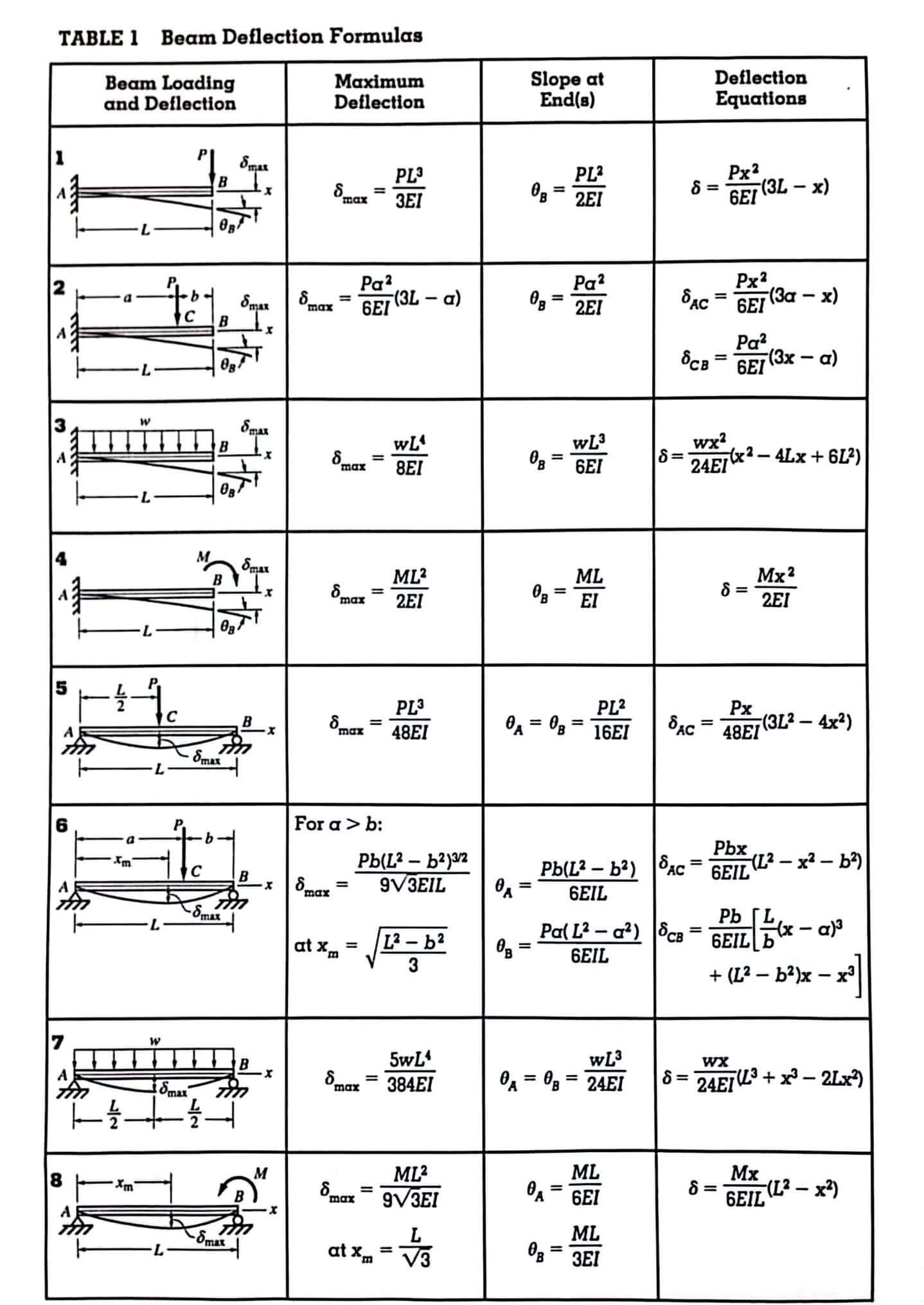
The General Workflow
- Simplify the Model: Represent the shaft as a beam with supports at the bearing centerlines.
- Calculate the Loads: Determine the forces acting on the shaft from gears, pulleys, etc.
- Apply Beam Formulas: Use superposition and formulas from a table (like the one above) to find the deflection and slope at critical points (e.g., at the gear and at the bearings).
Calculating Gear Forces
The primary loads on our rotary mechanism's shaft come from the gears. A gear mesh transmits a tangential force (), which transmits the torque, and a radial force (), which pushes the shafts apart.
Shigley 7.5 | Shaft Deflection | SolidWorks
Let's review how to calculate these forces. This video demonstrates the process for a gear train, which is directly applicable to our project.
Watch from 22:20 to 29:30. Focus on how the input torque is used to find the tangential force, and how the pressure angle is then used to find the radial force.
In summary, the key equations are:
- Tangential Force: , where is the torque and is the pitch radius of the gear.
- Radial Force: , where is the gear's pressure angle (commonly 20°).
These two forces act on the shaft at the gear's location. For a 3D analysis, you would typically analyze deflection in two planes (e.g., vertical and horizontal) and combine the results. For a quick estimate, you can find the resultant force and treat it as a single load.
Single-Load Simply-Supported Shaft Deflection & Slope | Preventing Excessive Gear Separation & Slope
Now, let's see how these concepts are put together to calculate the deflection of a shaft by hand.
Watch from 03:54 to 26:30. This is a complete walkthrough of a hand calculation. Notice how the problem is simplified to a 2D beam problem and how the standard formulas are applied. Don't worry about memorizing the formulas; focus on the process.
While powerful for simple, uniform-diameter shafts, hand calculations become tedious and less accurate for stepped shafts with multiple components. That's where FEA comes in.
3. The Detailed Validation: FEA in Onshape
For our project, which involves a more realistic stepped shaft, FEA is the more practical and accurate method. Your experience with FEA theory will be very helpful here as we focus on the practical setup in Onshape. The goal of the simulation is to find the Displacement of the shaft under load.
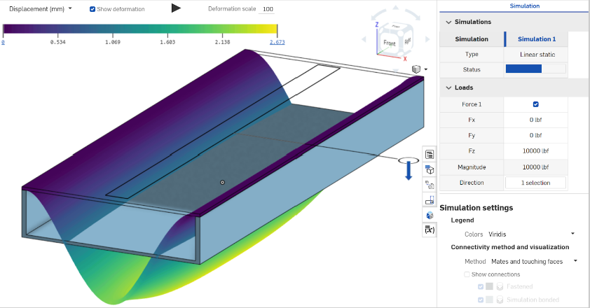
Here is the basic workflow for running a deflection analysis in Onshape.
This Onshape help article provides the step-by-step instructions for setting up a simulation. We will follow this general process.
First, quickly read the 'Basic workflow' section to get an overview of the process: Fix an instance, assign materials, add a load, and show results. Then, jump to the 'Simulation results and color scale' section and read about the 'Displacement' result option. This is the metric we're interested in.
Applying the Workflow to a Shaft
- Isolate the Part: While you can simulate in an assembly, it's often easiest to analyze a single shaft in its own Part Studio or a dedicated assembly.
- Assign Material: Ensure your shaft has a material assigned (e.g., 1045 Steel). The Young's Modulus (Modulus of Elasticity) is the critical property for deflection analysis.
- Apply Fixtures: To simulate simply supported bearings, use the Fix constraint on the cylindrical faces of the shaft where the bearings sit. This prevents translation but allows rotation, modeling an ideal bearing support.
- Apply Loads: Use the Force tool to apply the tangential () and radial () forces you calculated. Apply these forces to the faces of the shaft where the gear hub would sit. You will need to apply two separate Force loads (one for each direction) to the same region.
- Run and Interpret: Click Show results. In the results panel, select Displacement. The color plot will show the total deflection. You can hover your cursor over the gear location and bearing locations to get specific deflection and slope values.
Shigley 7.5 | Shaft Deflection | SolidWorks
This video, although demonstrated in SolidWorks, provides an excellent conceptual walkthrough of this exact process. The principles of setting up fixtures for bearings and applying forces are universal.
Watch from 15:50 to 21:12 to see how bearing fixtures are applied. Then, watch from 39:42 to 49:00 to see how the results are probed to find the maximum deflection and how those results are compared to allowable limits from a table.
Test your understanding!
In the video (at around 41:00), the instructor uses "Probe" on "on selected entities" to plot the deflection along the shaft's length. Why is this a better way to analyze the results than just looking at the color plot and finding the single point of maximum deflection?
Show answer
Plotting the deflection along the entire shaft provides much more information. It allows you to:
- Find the deflection at any point of interest, not just the maximum (e.g., at the specific locations of gears and bearings).
- Visually assess the shape of the deflected shaft (the elastic curve).
- Calculate the slope at any point (like at the bearings) by finding the gradient of the plotted line, which is critical for bearing alignment.
Looking only at the maximum deflection value tells you if you've exceeded a general limit, but the full plot is needed to check against all component-specific constraints.
4. If Deflection is Too High: Redesigning for Stiffness
What do you do if your analysis shows the deflection exceeds the allowable limits? For shafts, the most effective way to increase stiffness is to increase the diameter.
Recall from your mechanics courses that deflection () is inversely proportional to the area moment of inertia (). For a solid circular shaft, . Therefore:
This relationship is extremely powerful. A small increase in diameter leads to a large decrease in deflection. If you need to halve the deflection, you don't need to double the diameter. You can use the following formula to find a new required diameter:
This allows for a targeted redesign. If your analysis shows a deflection of 0.2 mm but your gear manufacturer specifies a maximum of 0.1 mm, you can calculate the necessary diameter increase to meet the requirement.
Conclusion
Today you've learned how to analyze one of the most critical aspects of shaft design: stiffness. A successful design isn't just about preventing breakage; it's about ensuring the entire system functions correctly, and controlling deflection is key to that.
Key Takeaways:
- Shaft deflection is a critical design constraint that affects gear and bearing performance.
- A dual approach of hand calculations (for estimation) and FEA (for accuracy) provides a robust validation workflow.
- The analysis process involves modeling the supports (bearings), applying loads (from gears/pulleys), and measuring the resulting displacement and slope.
- The results must be compared to allowable limits specified by component manufacturers or engineering standards.
- If a shaft is too flexible, the most effective way to increase stiffness is by increasing its diameter, as stiffness is proportional to diameter to the fourth power.
Preview of the Next Lesson:
We have now analyzed our design for strength (housing FEA), longevity (bearing life), and stiffness (shaft deflection). Next, we will take a step back and look at the system more holistically. We will conduct an FMEA for the rotary mechanism, assessing potential failure modes and their effects to proactively identify and mitigate risks in our design.