Hello! In our last lesson, we finalized the commercial aspect of our rotary mechanism design by developing a detailed Bill of Materials (BOM) and a preliminary cost estimate. With the design validated and its components itemized, we are now ready to create the primary technical communication tool in engineering: the formal drawing package.
The learning outcome for this lesson is to generate a complete set of engineering drawings, including assembly and key component views with GD&T. This process translates your 3D digital model into a set of unambiguous instructions for manufacturing, inspection, and assembly. For your portfolio, a professional drawing package is non-negotiable; it demonstrates a complete understanding of the engineering lifecycle, from concept to production-ready documentation.
1. The Role of Engineering Drawings
In an era of 3D CAD and automated manufacturing, you might wonder why 2D drawings are still essential. The answer is that a 3D model defines the perfect, nominal geometry, whereas a 2D drawing defines the allowable imperfections. It is the contract between the designer and the manufacturer.
To get a comprehensive overview of why drawings are critical and to understand their standard components, let's watch an excellent video on the topic.
Understanding Engineering Drawings
This video from The Efficient Engineer provides a fantastic foundation, covering everything from the purpose of drawings to the meaning of their various components.
Please watch the video from the beginning up to 14:43. Pay close attention to: The distinction between assembly drawings and detail drawings. The concept of orthographic projection (first vs. third angle). The purpose of different views like isometric, section, and detail views. Best practices for dimensioning and the role of a BOM on assembly drawings.
As the video explained, engineering drawings fall into two main categories, each with a distinct purpose. The article "How to Prepare a Perfect Engineering Drawing" provides a concise summary of this distinction.
| Feature | Part Drawing (Detail Drawing) | Assembly Drawing |
|---|---|---|
| Primary Purpose | Manufacturing of a single component. | Assembly of multiple components. |
| Level of Detail | High: Every feature fully dimensioned and toleranced. | Low: Only overall dimensions and part identification (balloons). |
| Key Components | Orthographic views, full dimensions, material spec, finish spec. | Exploded/section views, BOM, balloons, reference dimensions. |
| Target Audience | Machinist, fabricator, quality inspector. | Assembler, manufacturing engineer, maintenance technician. |
(Table adapted from Xometry's "How to Prepare a Perfect Engineering Drawing" article).
2. Creating Drawings in Onshape: The Fundamentals
Now, let's transition from theory to practice and see how to create these drawings in Onshape. The workflow is designed to be intuitive, building directly from your existing 3D models.
Onshape - Drawings Overview - How to Create New Drawings, Views, and Dimensions
This tutorial demonstrates the fundamental workflow for starting a new drawing in Onshape, selecting a template, and placing the essential views.
Watch from the beginning to 05:08. Focus on the mechanics of: Creating a new drawing from a part studio or assembly. Inserting a base view and changing its orientation. Creating projected orthographic views and an isometric view. Repositioning views and adjusting their properties (e.g., scale, hidden line display).
Beyond these basic views, Onshape allows you to create specialized views like Section Views to show internal features and Detail Views to magnify complex areas. You saw these mentioned in the first video, and you can create them using the tools in the top toolbar of the Onshape Drawing environment.
3. Creating a Detail Drawing for Manufacturing
A detail drawing must contain all the information necessary to manufacture a part without ambiguity. This means clear views, complete dimensions, and correctly specified tolerances.
Let's dive into a practical tutorial that covers not just the "how" but also the "why" of good dimensioning and tolerancing practices, which is directly relevant to your goal of producing professional-grade work.
This guide from a CAD course provides a step-by-step walkthrough for creating a fully-dimensioned part drawing, including a crucial discussion on tolerances.
Please read the first two sections, 'Creating Drawings & Dimensions' and 'Tolerances'. As you read, focus on the 'Pro Tips' which explain the real-world impact of your choices, such as: Aligning dimensions for readability. The connection between the number of decimal places on a dimension and the general tolerance block in the title block. How and why you would apply a specific, 'tighter' tolerance to a critical feature like a keyway.
Introduction to Applying GD&T
As a mechanical engineer, you know that dimensional tolerances (like ±0.01) control size, but they don't adequately control a part's form or function. This is where Geometric Dimensioning and Tolerancing (GD&T) comes in. GD&T is a symbolic language that allows you to control features like flatness, perpendicularity, and position relative to a functional reference frame.
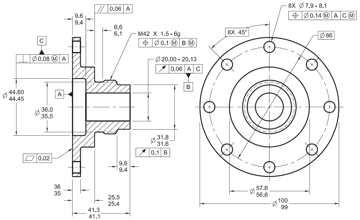
Applying GD&T is a hallmark of a professional drawing. Let's see how to implement it in Onshape.
The same tutorial provides a concise, practical introduction to applying GD&T in Onshape. It connects the CAD actions directly to the engineering intent.
Read the section 'Geometric Dimensioning & Tolerancing'. Focus on understanding the workflow for: Creating Datums: Establishing the reference frame for your measurements. Applying a Feature Control Frame: Defining a geometric control like Parallelism or Position. Using Basic Dimensions: These are theoretically exact dimensions whose tolerance is defined by a GD&T callout. The 'Pro Tip' explanations are excellent for clarifying what these callouts mean in a practical sense.
Test your understanding!
You are designing a mounting bracket. A critical requirement is that the top mounting surface must be parallel to the bottom mounting surface to ensure a stable installation. Simply dimensioning the height with a +/- tolerance isn't enough to guarantee this.
According to the resources, what GD&T tool would you use to explicitly control the parallelism between these two surfaces? What are the basic steps you would take in Onshape to apply it?
Show answer
You would use a Parallelism control.
The steps would be:
- Establish the primary mounting surface as a Datum (e.g., Datum A).
- Create a Geometric Tolerance (Feature Control Frame) on the second surface.
- In the dialog box, select the parallelism symbol (
||), specify the tolerance value (e.g., 0.05), and reference Datum A.
4. Creating the Assembly Drawing
The assembly drawing's purpose is to communicate how the product is put together. Its key components are:
- Views: Often an isometric or exploded view to show how parts relate to each other.
- Bill of Materials (BOM): The list of parts you created in the previous lesson.
- Balloons: Numbered circles that link components in the view to their corresponding line item in the BOM.
In Onshape, you can insert the BOM you already built directly onto the drawing sheet and then use the "Balloon" tool to automatically create and link the callouts.
5. Your Task: Create the Drawing Package for Project 2
It's time to apply these concepts to your Rotary Mechanism project. This task will form a major part of your project deliverable.
Task 1: Create a Detail Drawing (approx. 25-30 min)
- Choose one critical, custom-manufactured part from your Rotary Mechanism assembly (the main housing or a shaft are good candidates).
- Create a new drawing for this part using an appropriate ANSI or ISO template.
- Place the necessary orthographic views (front, top, side) and an isometric view to fully describe the part. Use a Section View if it helps clarify internal geometry.
- Fully dimension the part. Add centerlines to all holes and cylindrical features.
- Apply Tolerances:
- Ensure the general tolerances in your title block are defined.
- Apply a specific bilateral or symmetric tolerance to at least one critical dimension (e.g., a shaft diameter that mates with a bearing).
- Apply GD&T:
- Establish at least one Datum on a primary functional surface (like a mounting face).
- Apply at least one Feature Control Frame. A good starting point is a Position tolerance on a pattern of mounting holes or a Perpendicularity tolerance on a feature that should be 90° to your datum.
Task 2: Create an Assembly Drawing (approx. 10-15 min)
- Create a new drawing for your top-level Rotary Mechanism assembly.
- Insert an exploded view and a standard isometric or orthographic view.
- Insert the BOM table you developed in the previous lesson.
- Use the Balloon tool to add callouts to the main components in the exploded view, ensuring they match the item numbers in the BOM.
Conclusion
In this lesson, you've learned how to create the definitive documents that bridge design and reality. A complete, clear, and accurate drawing package is the signature of a professional engineer.
Key Takeaways:
- Detail drawings are for manufacturing a single part and must be fully defined with dimensions and tolerances.
- Assembly drawings are for putting the product together and use views, balloons, and a BOM to show how components are related.
- Tolerances define the acceptable range of variation, and the number of decimal places on a dimension is a direct instruction to the machinist about required precision.
- GD&T is a powerful symbolic language used to control a part's function by specifying allowable variation in its form, orientation, and location.
Preview of the Next Lesson:
With the design analyzed, costed, and documented, the final step in our project phase is to communicate our work. In the next lesson, we will prepare a design review presentation for the rotary mechanism project. You will learn how to structure your findings and technical data into a compelling narrative for an audience of engineering peers and managers.