Hello! Welcome back to our module on Detail Design and Tolerance Application.
In our last lesson, you learned how to establish a Datum Reference Frame (DRF), which creates a stable, functional coordinate system for a part. This was the crucial first step into the world of Geometric Dimensioning and Tolerancing (GD&T).
Today, we will build directly on that foundation. We will learn how to use GD&T to control the actual geometry of features. The learning outcome for this lesson is to apply form and orientation controls (e.g., flatness, perpendicularity) using GD&T symbols. These are two fundamental categories of geometric control that answer the questions: "How perfect does the shape of this feature need to be?" and "How is this feature angled relative to our reference frame?"
By the end of this lesson, you'll understand how to use these controls to move beyond simple +/- tolerances and specify a part's geometric requirements in a way that directly reflects its function.
1. The Language of GD&T: The Feature ControlFrame
Before we explore specific controls, we need to understand the syntax used to apply them. In GD&T, all geometric tolerances are defined within a Feature Control Frame. This is a rectangular box that contains all the necessary information to define a geometric requirement.
The video "Understanding GD&T" by The Efficient Engineer provides a clear and concise breakdown of the Feature Control Frame. Understanding its structure is essential for reading and creating GD&T callouts.
Please watch from 2:34 to 4:05. Focus on the three main components discussed: Geometric Characteristic Symbol: Identifies the type of control being applied. Tolerance Value: Defines the size of the tolerance zone. Note the use of the diameter symbol ⌀ to indicate a cylindrical zone. Datum References: Lists the datums (A, B, C) that the feature is being related to, in order of precedence.
Think of the Feature Control Frame as a complete sentence: it specifies what is being controlled, how much variation is allowed, and in relation to what reference it is being measured.
2. Category 1: Form Controls
Form controls are the simplest category of GD&T. They control the shape of an individual feature without relating it to any other feature. Because of this, form controls never use a datum reference in the feature control frame. They are used to refine the form of a feature beyond what is controlled by its size tolerance.
The four primary form controls are:
- Flatness: How flat a surface is.
- Straightness: How straight a line element on a surface or the axis of a cylinder is.
- Circularity (Roundness): How close to a perfect circle any cross-section of a cylinder, sphere, or cone is.
- Cylindricity: A composite control that checks for both roundness and straightness along the entire length of a cylinder.
Let's continue with the "Understanding GD&T" video for a quick overview of these four form controls and their tolerance zones.
Watch from 4:05 to 9:28. As you watch, pay attention to the shape of the tolerance zone for each control: Flatness: A zone between two parallel planes. Straightness: A zone between two parallel lines (for a surface) or a cylindrical zone (for an axis). Circularity: A zone between two concentric circles. Cylindricity: A zone between two concentric cylinders.
Practical Application: Surface vs. Feature of Size
It's crucial to understand how GD&T differentiates between controlling a surface and controlling a feature of size (like a pin or hole). The way the feature control frame is applied on the drawing changes its meaning entirely.
GD&T Lesson 2: Form Tolerances
The video "GD&T Lesson 2: Form Tolerances" by R. Dean Odell gives a more detailed, practical explanation of straightness. It clearly illustrates the difference between applying it to a surface versus the axis of a pin.
Please watch from 0:26 to 5:48. Notice the key visual difference on the drawing: Surface Straightness: The leader line points directly to the surface. Axis (Derived Median Line) Straightness: The feature control frame is placed directly under the feature's size dimension. This is a critical convention in GD&T.
This distinction is vital for design intent. For example:
- You might apply flatness to the primary datum surface of a mounting bracket to ensure it sits flush against its mating part.
- You might apply cylindricity to a shaft that will be fitted with a high-precision bearing to ensure smooth rotation.
- You might apply axis straightness to a long, slender pin to ensure it can be inserted into a deep hole without binding.
3. Category 2: Orientation Controls
While form controls manage the shape of a feature in isolation, orientation controls manage the angle of a feature relative to a datum. This is where your knowledge of Datum Reference Frames becomes essential. The feature control frame for an orientation control will always include at least one datum reference.
The three orientation controls are:
- Perpendicularity: Controls how close a feature is to a perfect 90° angle with a datum.
- Parallelism: Controls how close a feature is to being perfectly parallel (0°) with a datum.
- Angularity: The general case that controls a feature's orientation at any specified angle (other than 90° or 0°) to a datum.

Let's dive deeper into the two most common orientation controls.
Perpendicularity (⟂)
Perpendicularity is critical for parts that need to assemble squarely, like a bolt going through a plate or two faces meeting at a corner.
Perpendicularity in GD&T: Types and How to Measure It
The article "Perpendicularity in GD&T" from Wayken provides excellent visual explanations of the two main types of perpendicularity.
Please read the sections on "Surface Perpendicularity" and "Axis Perpendicularity". Pay close attention to the diagrams showing the tolerance zones. For a surface, it's two parallel planes at 90° to the datum. For an axis (like a hole), it's a cylindrical zone at 90° to the datum.
A common real-world application is ensuring that tapped holes on a flange face are perpendicular to that face. If they are not, the bolts will be crooked, leading to uneven clamping pressure and potential failure.
Parallelism (∥)
Parallelism ensures that two features remain a constant distance from one another across their entire surface.
Now, let's explore parallelism with an article from GD&T Basics. It provides a great industrial example that highlights why parallelism is more than just a geometric curiosity.
Please read the "Description," "GD&T Tolerance Zone," "Gauging / Measurement," and "Parallelism Example" sections. The gear example is particularly insightful. It shows how using parallelism can allow for a looser tolerance on the overall part thickness while still ensuring the critical faces are parallel for proper loading.
This gear example is a perfect illustration of designing for function. The overall thickness of the gear might not be as critical as the fact that its two faces must be parallel to distribute the axial load evenly. GD&T allows you to control what truly matters, often relaxing other, less critical dimensions, which can reduce manufacturing costs.
Test your understanding!
Let's return to the L-bracket from the previous lesson. It bolts to a vertical plate (Datum A), is located by a dowel pin (Datum B axis), and rests on a bottom support (Datum C).
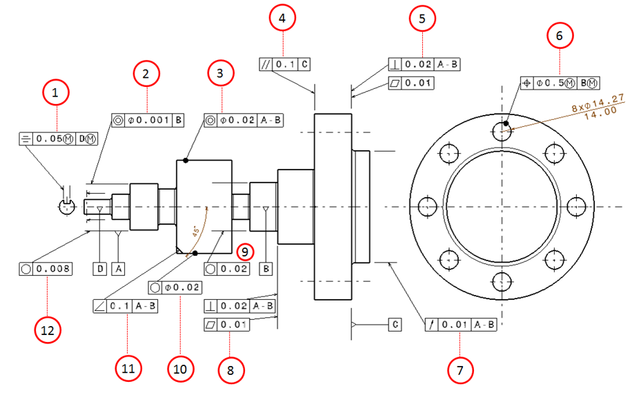
- To ensure the bracket mounts flush against the vertical plate, which form control would you apply to Datum A (the back face)? Where would you place the feature control frame?
- To ensure the dowel pin hole is drilled straight into the bracket, which orientation control would you apply to the hole? What datum would you reference in the feature control frame?
Show answer
-
You would apply a Flatness control to the back face (Datum A). This ensures the entire surface is smooth and free of high/low spots, allowing it to sit flush. The feature control frame would point to the surface and would contain only the flatness symbol and a tolerance value (e.g.,
| ▱ | 0.05 |). It would have no datum reference. -
You would apply a Perpendicularity control to the hole. This ensures the axis of the hole is at a 90° angle to the mounting face. You would reference Datum A in the feature control frame. The feature control frame would be placed under the hole's diameter dimension and would look something like this:
| ⟂ | ⌀0.1 | A |. The diameter symbol⌀indicates the tolerance zone for the hole's axis is a cylinder.
Conclusion
Today, you've added two powerful categories of tools to your engineering design toolkit. You now understand how to precisely specify the shape and orientation of features, which is fundamental to creating functional, manufacturable, and inspectable parts.
Key Takeaways:
- The Feature Control Frame is the standard syntax for applying all GD&T controls.
- Form Controls (Flatness, Straightness, Circularity, Cylindricity) define the shape of a feature in isolation and never use datums.
- Orientation Controls (Perpendicularity, Parallelism, Angularity) define a feature's angle relative to a datum or DRF.
- The placement of the feature control frame on a drawing is critical—pointing to a surface controls that surface, while placing it under a dimension controls the feature of size (e.g., its axis or center plane).
Preview of the Next Lesson:
We have controlled form and orientation, but what about the most common requirement in assemblies: making sure features are in the right place? In the next lesson, we will explore location and profile controls. You will learn about the Position tolerance, arguably the most powerful and widely used symbol in all of GD&T, which allows you to control the location of features like holes and slots with far more flexibility than traditional +/- dimensioning.