Hello! Welcome back to our module on Detail Design and Tolerance Application.
In our last lesson, we established a solid foundation by learning how to apply form and orientation controls like flatness and perpendicularity. You learned how to define the shape of a feature and its angle relative to a datum reference frame.
Today, we move on to two of the most powerful and commonly used categories in GD&T. Our learning outcome is to apply location and profile controls (e.g., position, profile of a surface) using GD&T symbols. These controls answer the fundamental questions: "Is this feature in the right place?" and "Does this complex surface have the right shape?" Mastering these will be a significant step in your ability to create precise and functional designs for your portfolio projects.
1. The Position Tolerance: The Workhorse of GD&T
In mechanical assemblies, the most frequent requirement is ensuring that parts fit together. This almost always comes down to controlling the location of features like holes, pins, and slots. While traditional +/- dimensioning can do this, it has limitations. The Position tolerance is the modern, more functional solution.
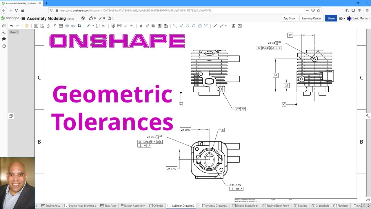
Position tolerance defines a zone within which the axis, center plane, or center point of a feature of size must be contained. To define where this zone is, we don't use +/- dimensions. Instead, we use basic dimensions.
To understand the core concepts of Position, True Position, and basic dimensions, let's turn back to the "Understanding GD&T" video from The Efficient Engineer. It clearly explains why this method is superior to traditional tolerancing.
Please watch from 14:07 to 16:53. Focus on these key ideas: True Position: The theoretically exact location of a feature, defined by basic dimensions (those shown in a box on the drawing). Cylindrical Tolerance Zone: Unlike the square zone created by +/- tolerances, the Position tolerance typically defines a cylindrical zone, which more accurately reflects the function of a pin in a hole. Datum Precedence: Notice how the feature control frame explicitly defines the order of datums, communicating the functional priority for inspection.
A Practical Method for Applying Position
Given your goal of simulating a real-world engineering workflow, let's use a systematic approach to applying Position tolerance.
How to Apply GD&T Position Tolerance to a Hole
The video "How to Apply GD&T Position Tolerance to a Hole" by Straight To The Point Engineering provides a simple, memorable workflow called the "pick three method."
Watch from the beginning to 3:10. This video walks you through the entire process: Pick Your Datums: Establish the datum reference frame (e.g., A, B, C) from which you will locate the feature. Pick Your Dimensions: Use basic (boxed) dimensions to define the feature's True Position relative to the datums. Pick Your Tolerance: Create the feature control frame, specifying the Position symbol (⌖), the tolerance value, and the datum references in order of precedence.
This method provides a clear, repeatable process that you can apply directly to your own designs in OnShape.
2. Unlocking Bonus Tolerance with Material Condition Modifiers
Here is where GD&T truly outshines traditional tolerancing, especially for a design engineer. By using material condition modifiers, you can link a feature's size to its positional accuracy, making parts easier and cheaper to manufacture.
The most important modifier is Maximum Material Condition (MMC), indicated by an (M) in the feature control frame.
- For a hole, MMC is its smallest allowable diameter (the most material is left on the part).
- For a pin, MMC is its largest allowable diameter (the pin itself contains the most material).
When you specify a Position tolerance at MMC, you are saying: "This tolerance applies when the feature is at its most difficult-to-assemble size." If the feature is produced away from its MMC size (e.g., a hole is drilled larger), you get an additional bonus tolerance.
Let's watch the next segment of the "Understanding GD&T" video, which explains this crucial concept of bonus tolerance.
Watch from 16:28 to 20:20. Pay close attention to the animated example of the hole. As the hole gets larger (departing from its MMC size), the positional tolerance zone for its axis also grows. This bonus is equal to the amount of departure from the MMC size.
This is not just a theoretical concept; it has direct real-world implications. It means a machinist doesn't have to hold an overly tight positional tolerance on a hole that is already oversized, because the larger hole provides more clearance for the mating pin anyway. This directly reduces manufacturing effort and cost.
3. Profile Tolerances: The "Swiss Army Knife" of GD&T
What if you need to control a surface that isn't a simple plane or cylinder? Think of the ergonomic grip on a power tool, the aerodynamic surface of a car body panel, or a complex cast housing. For these, we use Profile tolerances.
There are two profile controls: Profile of a Line and Profile of a Surface. We will focus on Profile of a Surface, as it is a 3D control and is exceptionally versatile.
The article "Profile of a Surface" on GD&T Basics provides an excellent, in-depth look at this powerful control.
Please read the "Description" and "When Used" sections. Note two key points: The tolerance zone is a 3D boundary of uniform thickness that follows the true profile of the surface. When used with datums, Profile of a Surface can control size, location, orientation, and form all at once. This makes it a 'catch-all' symbol for controlling any surface.

Practical Insights on Profile
Your experience in automotive and mechanical design means you've likely encountered many complex surfaces on cast, molded, or forged parts. Profile is the go-to tool for controlling these. Here are some industry-relevant points from the comments section of the GD&T Basics article you just read:
- Model-Based Definition (MBD): It's common practice in modern CAD-centric workflows to apply a general profile tolerance to the entire part in the drawing notes (e.g., "UNLESS OTHERWISE SPECIFIED, ALL SURFACES |⌒| 0.5 | A | B | C |"). This note, combined with the "basic" dimensions defined by the 3D CAD model, fully defines the part's geometry without cluttering the drawing with thousands of dimensions.
- Bilateral vs. Unilateral: By default, a profile tolerance of
0.5creates a zone of+/-0.25around the true surface. However, the ASME standard allows for an unequally disposed or unilateral tolerance zone (using a(U)modifier), which is useful for situations like adding material for a coating or removing it via wear.
Test your understanding!
Imagine you are designing a cover plate for an engine component.
- The plate has four M6 clearance holes for bolts.
- The top surface of the plate is a complex, ergonomic shape designed to be a handle.
- The plate mounts onto a flat surface (Datum A) and is aligned by two dowel pins (which establish Datums B and C).
- To ensure the four M6 holes align with the tapped holes in the engine block, which GD&T control would you use? What modifier would be extremely useful to include in the feature control frame to reduce manufacturing costs?
- To control the complex shape of the handle surface, which GD&T control would you use? How would it relate to the datums?
Show answer
- You would use the Position (⌖) tolerance to control the location of the four holes. You would include the MMC modifier
(M)in the feature control frame (e.g.,| ⌖ | ⌀0.2 (M) | A | B | C |). This allows for bonus tolerance if the clearance holes are made larger than their minimum size, making the part easier to manufacture. - You would use the Profile of a Surface (⌒) tolerance. Since the shape of the handle needs to be correctly formed and correctly located relative to the mounting face, you would reference the datums in the feature control frame (e.g.,
| ⌒ | 0.8 | A | B | C |). This single callout controls the handle's form, orientation, and location.
Conclusion
You've now covered the final, and arguably most impactful, categories of geometric controls. With Form, Orientation, Location, and Profile, you have a comprehensive set of tools to precisely define part geometry.
Key Takeaways:
- Position (⌖) is the standard for controlling the location of features of size like holes and slots. It uses basic dimensions to define a true position.
- The MMC modifier
(M)is a powerful tool used with Position to gain bonus tolerance, which connects design intent with manufacturing reality. - Profile of a Surface (⌒) is a highly versatile control for defining complex surfaces. When used with datums, it can simultaneously control form, orientation, and location.
- As a simple rule of thumb: if you are locating a feature of size, use Position. If you are controlling a surface or shape, use Profile.
Preview of the Next Lesson:
So far, we have focused on which GD&T controls to use and how to apply them. But how do you choose the actual number in the tolerance block? A tolerance of 0.01 is very different from 1.0. In our next lesson, we will address this by learning how to select tolerances appropriate for a given material and manufacturing process.