Hello! Welcome to the next lesson in our module on Detail Design and Tolerance Application.
In our last session, we dove into worst-case tolerance stack-up analysis. You learned how to trace a dimensional loop and calculate the maximum possible variation in an assembly. A key takeaway was that relying solely on simple +/- tolerances can sometimes force you into using very tight, expensive-to-manufacture dimensions to ensure parts fit.
Today, we'll begin exploring a more powerful and precise language for controlling part geometry: Geometric Dimensioning and Tolerancing (GD&T). Our learning outcome is to specify datums on engineering drawings to establish datum reference frames. This is the absolute foundation of GD&T. Think of it as creating a stable, functional coordinate system for your part, from which all other critical features will be measured and inspected.
1. From Variation to a Stable Foundation
Before we can control complex features, we need a common, unambiguous frame of reference. This is what the Datum Reference Frame (DRF) provides. In manufacturing and inspection, a physical part is never perfect; it has variation. The DRF is the theoretically perfect coordinate system we anchor to the real-world part.
To start, let's clarify the key terms.
Mastering GD&T - Building Datum Reference Frames
The article "Mastering GD&T - Building Datum Reference Frames" from Five Flute provides excellent, concise definitions for the core concepts we'll be discussing. Understanding this terminology is crucial.
Please read the section "Basic Terminology and Definitions." Focus on the distinction between: Datum: The theoretically perfect plane, axis, or point. Datum Feature: The real, physical feature on your part (e.g., a surface, a hole). Datum Reference Frame (DRF): The complete, three-dimensional coordinate system built from three mutually perpendicular datum planes.
Every physical part exists in 3D space and has six degrees of freedom (DOF): three translations (movement along X, Y, and Z axes) and three rotations (rotation about the X, Y, and Z axes). The primary purpose of a DRF is to systematically lock down these degrees of freedom so the part's orientation is fully defined.

2. The 3-2-1 Rule: Building the Frame
We build the DRF by selecting datum features in a specific order of importance, known as datum precedence. We select a Primary (A), Secondary (B), and Tertiary (C) datum feature. This sequence isn't arbitrary; it reflects how the part functions in its assembly and how it should be fixtured for manufacturing and inspection.
This process follows the 3-2-1 Rule, which describes how each successive datum constrains the part.
Datum Reference Frame Overview
The video "Datum Reference Frame Overview" by GD&T Basics provides an excellent animated explanation of how the 3-2-1 rule works to constrain all six degrees of freedom.
Please watch from the beginning to 4:08. Pay close attention to: The introduction to the six degrees of freedom (0:02 - 0:56). The animation showing how Primary Datum A (a plane) contacts on 3 points, constraining 3 DOF. Then, how Datum B contacts on 2 points, constraining 2 more DOF. Finally, how Datum C contacts on 1 point, constraining the final DOF (0:56 - 4:08).
As the video demonstrates:
- Primary Datum (A): The first feature to contact the inspection setup (e.g., a surface plate). It requires a minimum of 3 points of contact and constrains 3 DOF (one translation, two rotations).
- Secondary Datum (B): The second feature to make contact. It requires a minimum of 2 points of contact and constrains 2 more DOF (one translation, one rotation).
- Tertiary Datum (C): The final feature. It requires a minimum of 1 point of contact and constrains the final degree of freedom (one translation).
3. Datum Precedence and Design Intent
The order in which you call out the datums (A, then B, then C) is critical because it dictates the design intent. The primary datum is the most important functional feature, followed by the secondary, and then the tertiary. Changing the order changes how the part is fixtured and inspected, and therefore changes which features are held most stable.
This is not just an academic point; it has huge real-world implications for whether your part will function correctly.
Datum Reference Frame Overview
Let's continue with the "Datum Reference Frame Overview" video to see a practical example of how changing datum precedence completely alters the design intent.
Please watch from 4:08 to 7:55. This segment demonstrates two scenarios: Plane-Cylinder-Slot: The flat face is primary (Datum A), meaning the part must sit flat on that face first, before the cylindrical boss (Datum B) is centered. Cylinder-Plane-Slot: The cylindrical boss is primary (Datum A), meaning the part must be centered by the cylinder first, even if the face isn't perfectly flat against its mating surface. Notice how the assembly animation and the inspection setup change based on this choice.
The key principle, as stated in the video, is: The datum reference frame must mimic the part's functionality in the assembly.
4. How to Select and Specify Datums on a Drawing
Now for the most practical part: How do you choose the right features to be your datums, and how do you represent them on an engineering drawing?
Choosing Datum Features
Your choice of datums should be driven by the part's function. Ask yourself:
- How does this part mount or assemble?
- What is the main locating surface? (Often becomes Primary Datum A)
- What feature prevents it from sliding? (Often becomes Secondary Datum B)
- What feature "clocks" it or stops it from rotating? (Often becomes Tertiary Datum C)
Datum Reference Frames (DRFs) in GD&T
The article "Datum Reference Frames (DRFs) in GD&T" from Jiga provides excellent, straightforward guidelines for selecting good datum features.
Please read the sections "Guidelines to choosing Datum Features" and "Common mistakes in DRF selection." This will give you a practical, industry-focused checklist for making good design decisions.
Specifying Datum Features
Once chosen, you identify datum features on a drawing using the Datum Feature Symbol. This is a capital letter in a square frame with a leader line pointing to the feature. The way you place this symbol is critical.
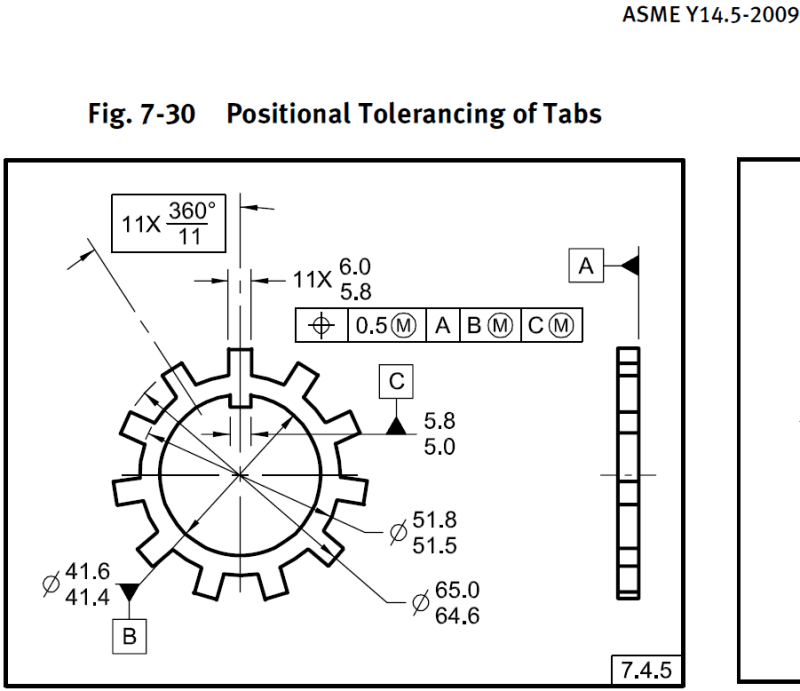
The placement of the symbol defines what the datum is. For example, placing it on a surface makes that surface the datum feature. Placing it in line with a dimension for a feature of size (like a hole or a width) makes the centerline or center plane of that feature the datum.
Mastering GD&T - Building Datum Reference Frames
Let's return to the Five Flute article, which has a fantastic table summarizing how different types of features can be used as datums and how they constrain the part.
First, review the table in the section "Defining DRFs by selecting datum features." It clearly connects the drawing callout to the type of feature and the constraints it imposes. Then, read the final section "Theory into practice: two example parts for building DRFs." The sheet metal bracket example is particularly relevant, as it uses a face, a hole, and a slot to establish its DRF—a very common scenario in mechanical design.
Test your understanding!
Imagine you are designing a simple L-bracket that bolts onto a large, flat vertical plate. A dowel pin goes through the hole on the bracket and into the plate to provide precise alignment. The bottom edge of the bracket rests on a support surface.
Based on this functional description, what features would you choose for your Primary (A), Secondary (B), and Tertiary (C) datums? Justify your choices in terms of the 3-2-1 rule and constraining degrees of freedom.
Show answer
A logical datum scheme based on the function would be:
-
Primary Datum (A): The large back face that bolts against the vertical plate.
- Justification: This is the primary mounting interface. It establishes the main orientation of the bracket. It's a large, stable plane that can make at least 3 points of contact, constraining one translation (Z-axis) and two rotations (about X and Y axes).
-
Secondary Datum (B): The axis of the dowel pin hole.
- Justification: The dowel pin provides precise location relative to the mounting plate. As a feature of size, its axis can establish at least 2 points of contact with the inspection fixture (e.g., an expanding pin). It constrains two more degrees of freedom: translation in X and Y. At this point, the only freedom left is rotation about the Z-axis.
-
Tertiary Datum (C): The bottom edge that rests on the support.
- Justification: This edge prevents the bracket from rotating ("clocking") around the dowel pin. It makes at least 1 point of contact and constrains the final rotational degree of freedom (about the Z-axis).
With this A-B-C scheme, the part is now fully constrained in a way that mimics its real-world assembly.
Conclusion
You've just learned the single most important concept in GD&T. By establishing a functional Datum Reference Frame, you create an unambiguous foundation for dimensioning and inspection that directly relates to your design intent.
Key Takeaways:
- A Datum Reference Frame (DRF) is a theoretically perfect coordinate system used to constrain a part's six degrees of freedom.
- The DRF is built from datum features (real surfaces/features on the part) selected in order of functional importance: Primary (A), Secondary (B), and Tertiary (C).
- The 3-2-1 rule describes how datums A, B, and C progressively lock down the part's movement and rotation.
- Datum precedence is critical. The order A-B-C must mimic how the part assembles and functions to ensure correct manufacturing and inspection.
Preview of the Next Lesson:
Now that we know how to establish a stable reference frame, what do we do with it? In the next lesson, you will learn how to apply form and orientation controls (e.g., flatness, perpendicularity) using GD&T symbols. These controls allow you to define the shape of a single feature (like Datum A) and control the orientation of other features relative to your new DRF.