Hello! Welcome to the next lesson in our module on advanced mechanical components.
In our last session, we focused on securing components in metal assemblies using standard parts like retaining rings and locknuts. Now, we'll shift our focus to plastic parts, where fastening features are often integrated directly into the component geometry to reduce part count and simplify assembly.
This lesson addresses the learning outcome: Design cantilever snap-fits for plastic components. We will cover the fundamental mechanics, the design calculations you'll perform as an engineer, and the critical manufacturing considerations that influence the final geometry. This is a core skill for designing enclosures, consumer products, and automotive interiors.
1. Anatomy of a Cantilever Snap-Fit
A cantilever snap-fit is essentially a small, flexible finger with a hook that deflects during assembly and "snaps" back to lock two parts together. It's an elegant way to create a fastening without any extra hardware.
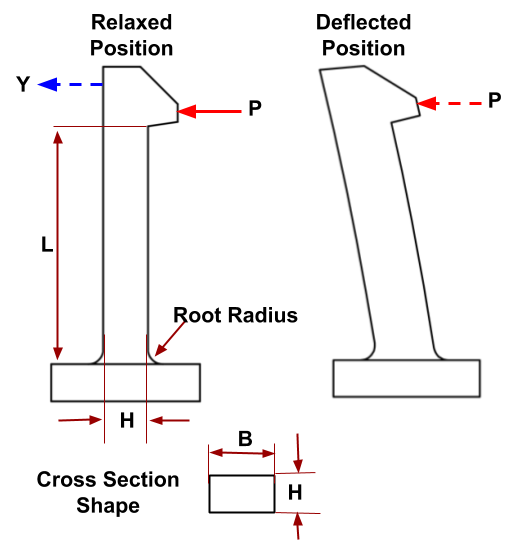
The key components you'll design are:
- Beam (or Arm): The cantilever portion that flexes. Its length () and thickness () are the primary drivers of its flexibility and strength.
- Hook: The feature at the end of the beam that engages with the mating part. The depth of the hook is called the undercut or overhang (). This is the distance the beam must deflect to assemble.
- Root: The base of the beam where it joins the main part wall. This area experiences the highest stress, making the root radius a critical feature for preventing failure.
The most common type of snap-fit used in engineering is the cantilever design, which will be our focus.
2. The Engineering Design Principles
As a design engineer, your primary goal is to find the right balance: the snap-fit must be flexible enough to assemble without breaking, but strong and stiff enough to hold the parts together securely. This balance is achieved through careful geometric design and material selection.
Your background in mechanics of materials will be very useful here, as the design process is a direct application of beam theory.
Let's dive into two excellent industry guides that cover the necessary theory and practical considerations.
First, we'll consult the 'Snap-Fit Design Manual' from BASF. This guide lays out the fundamental concepts and critical design rules.
First, read Part III: Snap-Fit Design Using Classical Beam Theory (pages III-1 to III-3). Focus on understanding the key terms: overhang depth, entrance angle, and retraction angle. Note the basic formulas for stiffness (k) and strain (ε). Then, jump to Part VI: General Design Guidelines (pages VI-1 to VI-2). Pay close attention to the section on 'Stress Concentration' and the recommended fillet radius. This is a critical point for avoiding failure, directly related to the principles of FMEA.
Key Design Parameters and Calculations
From that reading, you saw that the design process revolves around controlling the strain in the beam. The maximum strain () occurs at the root of the beam during the maximum deflection (). For a simple cantilever beam of uniform rectangular cross-section, the formula is:
Where:
- is the maximum strain at the root.
- is the deflection (the depth of the hook/undercut).
- is the beam thickness.
- is the beam length.
Your job is to ensure that this calculated strain is less than the allowable strain () for your chosen plastic material. Exceeding this limit will cause the snap to either break on the first use or fail prematurely.
Test your understanding!
Looking at the strain formula, which parameter has the most significant impact on reducing strain? In other words, if you need to decrease the strain in your design, which variable would you try to change first for the biggest effect?
Show answer
The beam length, . Because it is squared in the denominator, a small increase in length provides a large decrease in strain. Doubling the length reduces the strain by a factor of four. Conversely, thickness () is in the numerator, so a thicker beam increases strain.
A Practical Design Workflow with Worked Example
Now, let's put this into a step-by-step process using a second industry guide that provides an excellent worked example. This guide also introduces the idea of tapering the beam, which distributes stress more evenly and is a more materially efficient design.
Snap-Fit Joints for Plastics - A Design Guide
The 'Snap-Fit Joints for Plastics' design guide from Covestro offers a very clear, step-by-step calculation example that mirrors what you'd do in practice.
Please read the following sections: Design Hints (Page 7): Note the advice on tapering the beam and the discussion on root radius (R/h ratio). Calculations (Pages 8-14): Skim this to see the formulas. Don't worry about memorizing them. Pay special attention to Table 2 for allowable strain values and Figure 16 for the Secant Modulus chart, as these provide the necessary material data. Calculation example I (Page 15): Study this example carefully. It shows how to use the formulas and charts to go from requirements (material, undercut) to a final design dimension (beam thickness), and then calculate the resulting forces.
The workflow demonstrated in that example is exactly what you would follow:
- Define Requirements: Choose your material (e.g., Polycarbonate), and define the geometry (undercut , length ).
- Find Material Properties: Look up the allowable strain () from a table and the secant modulus () from a chart for that strain level.
- Calculate Geometry: Rearrange the appropriate strain formula to solve for the required beam thickness ().
- Calculate Forces: Use the force equations to determine the deflection force () and the final mating force (), which includes friction.
3. Design for Manufacturing (DFM): The Undercut Problem
Designing a functional snap-fit is only half the battle. As an engineer preparing a part for production, you must consider how it will be made. For plastic parts, the most common high-volume process is injection molding.
A standard injection mold consists of two halves (a core and a cavity) that pull apart in one direction. A snap-fit hook creates an undercut—a feature that blocks the mold from pulling away, trapping the part.
Dealing with undercuts is a critical DFM skill. Let's see how it's handled in a professional setting.
Injection Molding - Undercuts (How to Avoid and Design)
A key part of 'real-life' design is considering how the part will be manufactured. This video from Protolabs, an industry leader in rapid manufacturing, clearly explains the undercut issue and a common, clever design solution.
Please watch these three segments: What is an undercut? (00:20 - 00:51): This explains the core problem with a simple visual. Shut-offs (01:02 - 01:20): This introduces the elegant design solution for snap-fits. Fusion 360 Demo (02:43 - 05:17): Watch how the designer modifies the part to create an opening (a 'shut-off' or 'pass-through core') under the cantilever arm. This makes the part moldable without a complex, expensive 'side-action' in the mold. Notice that they also add draft to the new surfaces.
The key takeaway is that by adding an opening in the wall behind the snap-fit arm, you allow a portion of the mold steel to "shut off" against the other half, forming the hook feature without it becoming trapped. This is a far more cost-effective solution than requiring a complex mold with moving side-actions.
4. Practical Modeling and Iteration
Finally, let's look at the process of modeling a snap-fit in CAD and refining the design. The following video demonstrates this process for a part intended for 3D printing. While the manufacturing constraints are different (undercuts are generally not an issue in FDM printing), the design iteration process is universal and highly relevant.
Snap 3D prints together with cantilever joint - Fusion 360 tutorial
This tutorial shows how these features are modeled and, more importantly, how a design is refined after prototyping. Pay close attention to the iteration process, where the initial design's flaws are identified and corrected.
Watch the following parts: Sketching the Cantilever (01:48 - 04:29): Observe how the basic geometry of the arm and the hook is created from a 2D sketch and extruded. Identifying and Fixing Issues (07:32 - 11:46): This is the most important part. The presenter shows that the first prototype is loose and has alignment problems. Watch how they add features (ribs and grooves) to improve the fit and alignment. This highlights that your first design is a starting point, and testing—even digitally with FEA or with a quick prototype—is essential.
Conclusion
In this lesson, we explored the design of cantilever snap-fits, a fundamental technique for creating integrated fasteners in plastic components.
Key Takeaways:
- Snap-fit design is a practical application of beam theory, balancing flexibility for assembly with stiffness for retention.
- The primary design calculation ensures that the strain induced by deflection () does not exceed the material's allowable strain ().
- Small geometric details are critical: a generous root radius is essential to prevent stress concentration and failure, while entrance/retraction angles on the hook control assembly/disassembly forces.
- Design for Manufacturing (DFM) is paramount. For injection molding, you must account for the undercut created by the hook, often by designing in a "shut-off" or pass-through feature.
- Design is an iterative process. Your initial calculations provide a strong starting point, but refinement is often needed to perfect the fit and function.
Preview of the Next Lesson:
We've now covered several types of advanced components used in static or quasi-static assemblies. In the next lesson, we will shift gears to dynamics and explore how to "Analyze velocity and acceleration in linkage mechanisms using software tools." This will move us from designing the parts themselves to analyzing the motion of the systems they create.