Hello! Welcome to your next lesson on advanced mechanical components.
In our previous session, you learned how to design cantilever snap-fits, an ingenious method for joining plastic components. Today, we turn our attention back to metal assemblies and explore one of the most robust and fundamental methods for joining cylindrical parts: interference fits, also known as press or shrink fits.
This lesson covers the learning outcome: Calculate and design interference fits for mechanical assemblies.
We'll start with the underlying physics of how interference creates a powerful joint. Then, we'll walk through the essential calculations an engineer performs to determine the joint's strength, the force needed for assembly, and the torque it can transmit. Finally, we'll put it all together into a practical design workflow, showing how to use industry standards to specify a fit that meets performance requirements while accounting for manufacturing tolerances and material properties. This is a core skill for designing assemblies with gears, bearings, pulleys, and other shaft-mounted components.
1. The Fundamental Principle: Pressure from Interference
An interference fit is conceptually simple: the shaft is intentionally made slightly larger than the hole. Forcing them together creates immense radial pressure at the interface. This pressure generates a strong frictional force that locks the components, allowing them to transmit torque and axial loads without keys, splines, or fasteners.
Practical Ultimate Guide to Press Fit Calculations
To start, let's read a brief introduction that explains this core concept from the 'Practical Ultimate Guide to Press Fit Calculations'.
Please read the first two sections, 'What is the fundamental principle behind a press fit?' and 'How does interference generate contact pressure?'. Focus on the relationship between dimensional overlap (interference), the material's elastic reaction (Young's Modulus), and the resulting contact pressure.
As the reading highlights, this process creates elastic deformation. The outer component (hub) is stretched, and the inner component (shaft) is compressed. This stored potential energy results in two primary types of stress:
- Radial Stress: Acts perpendicular to the surface, compressing the shaft and putting the hub's inner wall in tension.
- Tangential (or Hoop) Stress: Acts along the circumference. This is compressive for the shaft and tensile for the hub.
Understanding and controlling these stresses is the key to a successful design. Exceeding the material's yield strength will cause permanent damage.
2. The Core Engineering Calculations
When designing an interference fit, there are three primary questions you need to answer:
- How much pressure is generated at the interface?
- How much force is required to press the parts together?
- What is the maximum torque the joint can transmit before slipping?
The following video provides a clear derivation and explanation of the formulas used to answer these questions.
How Much Force Is Needed for A Press Fit?
This video from the Engineering Educator Academy walks through the key parameters and formulas for analyzing an interference fit. Pay close attention to how the input variables (geometry, material properties, and interference) relate to the outputs (pressure, force, and torque).
Please watch the following segments: Explanation of Formulas (02:20 - 07:46): This section introduces the governing equations for pressure, assembly force, and transmissible torque. Note the variables involved, especially the material properties (Young's Modulus E, Poisson's Ratio \nu) and geometric terms (diameters d_o, d, d_i). Final Calculations (11:25 - 18:44): Observe the final calculated values and the units. The video demonstrates that a small interference can produce very large pressures, forces, and torque capacities. It also touches on the importance of checking these stresses against the material's limits.
Summary of Key Formulas
The video provides the generalized formulas which are based on Lamé's equations for thick-walled cylinders. Let's summarize the key relationships:
-
Contact Pressure (P): The pressure is directly proportional to the radial interference () and depends on the stiffness and geometry of both the shaft and hub.
Where is the nominal radius, and the subscripts and denote hub and shaft, respectively. For a solid shaft, . -
Assembly Force (F): This is the frictional force that must be overcome. It's the contact pressure multiplied by the contact area and the coefficient of static friction ().
-
Transmissible Torque (T): This is the frictional force acting at the nominal radius.

3. A Practical Design Workflow
In a real-world scenario, you often start with a performance requirement, such as the torque an assembly must transmit. Your task is to determine the necessary interference and specify manufacturable dimensions to achieve it.
From Torque Requirement to Interference
This is the most common design path. You work backward from the required torque to find the necessary interference.
Mastering Interference Fit: The Ultimate Guide
The article 'Mastering Interference Fit' provides an excellent five-step process that mirrors a professional engineering workflow. It shows you how to translate a torque requirement into a physical dimension.
Please read the section titled 'How do you calculate the required interference for a given torque?'. Focus on the logical sequence: Start with torque and apply a safety factor. Calculate the tangential force needed. Use the friction coefficient to find the required normal force. Determine the interface pressure from the normal force and area. Use Lamé's equations to solve for the dimensional interference.
This workflow is the core of interference fit design. It directly connects the performance specification to the physical design parameters.
Specifying Tolerances with ISO Fits
Once you've calculated the required interference, you need to translate it into dimensions and tolerances for an engineering drawing. The ISO 286 system provides a standardized way to do this. A fit is specified by a code, like H7/p6, which defines the tolerance zones for the hole and shaft.
- H7: An "H" hole means its minimum size is the nominal diameter. The "7" indicates the tolerance grade (the size of the tolerance band).
- p6: A "p" shaft means its tolerance zone is entirely above the nominal diameter, guaranteeing interference. The "6" is its tolerance grade.
Test your understanding!
Given two ISO interference fits, H7/p6 and H7/u6, which one would you expect to provide a greater interference and therefore a higher torque capacity? (Hint: The letters for shaft fits proceed alphabetically for looser fits to tighter fits.)
Show answer
H7/u6. The letter "u" comes later in the alphabet than "p", indicating a larger fundamental deviation from the nominal size. This means a u6 shaft will be larger than a p6 shaft of the same nominal size, creating a greater interference and higher torque capacity.
Worst-Case Analysis: The Role of Tolerances
Because all manufactured parts have tolerances, your calculated interference is not a single value but a range. You must analyze the two extremes:
- Maximum Interference: Occurs with the largest possible shaft and the smallest possible hole. This creates the highest stresses. You must check that these stresses do not exceed the yield strength of the materials. Failure to do so can cause the hub to crack or the shaft to yield.
- Minimum Interference: Occurs with the smallest possible shaft and the largest possible hole. This creates the lowest contact pressure. You must check that the torque capacity at this minimum pressure is still sufficient to meet your requirements (including the safety factor).
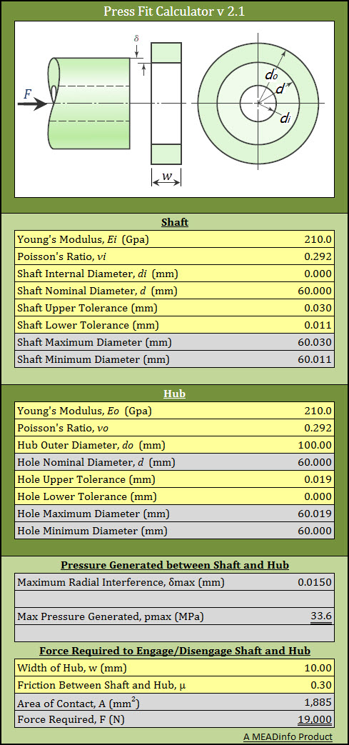
4. Critical Real-World Considerations
A successful design goes beyond the basic formulas and considers factors that affect performance in service.
-
Surface Finish: The formulas assume perfectly smooth surfaces. In reality, microscopic peaks (asperities) on the mating surfaces are crushed during assembly. This reduces the effective interference. A rougher surface finish results in a greater loss of interference. You must account for this, especially for critical applications. For very precise fits, a finer surface finish (e.g., grinding or honing) is required.
-
Material Combinations & Temperature: If the shaft and hub are made of different materials (e.g., a steel shaft in an aluminum hub), their different coefficients of thermal expansion (CTE) are critical. Aluminum expands nearly twice as much as steel for a given temperature increase.
- At high temperatures: The aluminum hub will expand more than the steel shaft, reducing the interference and potentially causing the joint to slip.
- At low temperatures: The aluminum hub will shrink more than the steel shaft, increasing the interference and stresses, potentially causing the hub to yield or crack.
Your design must be safe across the entire operating temperature range.
Conclusion
In this lesson, you've learned the principles and practical calculations behind designing robust interference fits. This is a powerful technique for creating strong, permanent joints in mechanical assemblies.
Key Takeaways:
- Interference fits use a dimensional overlap to create contact pressure and frictional force, allowing for the transmission of torque and axial loads.
- The core design process involves calculating the contact pressure, assembly force, and transmissible torque based on the fit's geometry, material properties, and the amount of interference.
- A practical design workflow often starts with a torque requirement and works backward to determine the necessary interference.
- ISO fit standards (e.g., H7/p6) are used to specify manufacturable dimensions and tolerances.
- Worst-case analysis is critical: you must check that the minimum interference prevents slipping and the maximum interference does not cause material failure.
- Real-world factors like surface finish and differential thermal expansion must be considered for a robust design.
Preview of the Next Lesson:
With this lesson, we conclude our deep dive into specific component-level joining and design techniques. Next, we will broaden our scope to analyze the motion of entire systems. The upcoming lesson, "Analyze velocity and acceleration in linkage mechanisms using software tools," will shift our focus from static strength to dynamic behavior.