Hello! Welcome back to our module on Advanced Mechanical Components and Powertrains.
In our last lesson, we covered the design of bolted joints, focusing on how to use preload to create strong, reliable connections for static components. Today, we shift our attention from holding things still to enabling smooth and reliable motion. Any machine with a rotating shaft—from a car's transmission to a factory conveyor—relies on bearings to do its job.
This lesson will address the learning outcome: Select and integrate standard bearings into an assembly based on load and life calculations. We will cover the standard industry process for choosing a bearing that not only fits but is also predicted to last for its required service life. As a design engineer, this is a fundamental skill for ensuring the reliability and longevity of any mechanical system you create.
1. The First Step: Calculating Bearing Loads
Before you can select a bearing, you must understand the forces it needs to withstand. These forces can be radial (acting perpendicular to the shaft's axis) or axial (acting parallel to the shaft's axis, also called thrust).
A common scenario in machine design involves a shaft supported by two bearings, with a load applied somewhere along its length, such as from a pulley or gear. Your background in statics is directly applicable here. We can model the shaft as a simple beam to find the reaction forces at the bearing locations.
To see this in action, let's watch a short video that clearly explains how to calculate these reaction loads.
Video Bearing Load Calculations
This video from Aaron Schellenberg demonstrates how to calculate radial loads on a two-bearing system with an overhung load, using basic principles of static equilibrium.
Please watch from the beginning to 04:49. Pay close attention to: How the forces from a V-belt drive create a total radial load on the shaft. The use of moment and force balances to calculate the individual reaction forces at Bearing A and Bearing B. The critical role that the overhung distance and the bearing spacing play in determining the magnitude of these loads.
As the video demonstrates, the loads on the bearings are a direct result of the system's geometry and the external forces. A key design takeaway is that minimizing the overhung distance and maximizing the spacing between bearings can significantly reduce the loads, leading to longer bearing life and the ability to use smaller, less expensive components.
2. The Core of Bearing Selection: Calculating L10 Life
A common misconception is that there's a direct formula to calculate the size of a bearing. The standard engineering practice is actually an iterative process:
- Make an initial bearing selection based on constraints like shaft diameter.
- Calculate the predicted life of that bearing under the specific operating conditions.
- Compare the calculated life to the required life for the application.
- If the life is insufficient, select a larger or more capable bearing and repeat the calculation.
The cornerstone of this process is the basic rating life, L10.
What is L10 Life?
Bearing failure from material fatigue is a statistical phenomenon. If you test a large batch of identical bearings under identical conditions, they won't all fail at the same time. The L10 life is the number of revolutions that 90% of the bearings in that group will successfully complete or exceed before the first signs of fatigue appear. It is sometimes called the "B10" life and represents a 90% reliability.
To calculate this, we use the following fundamental equation:
Where:
- is the basic rating life in millions of revolutions.
- is the Basic Dynamic Load Rating, found in the manufacturer's catalog. It represents the constant load a bearing can endure for exactly one million revolutions.
- is the Equivalent Dynamic Load, which is the calculated constant load that would have the same effect on bearing life as the actual combination of radial and axial loads.
- is the life exponent, which is 3 for ball bearings and 10/3 for roller bearings.
Let's watch a video that explains these concepts and walks through a full calculation.
Bearing Size Calculation | Basic Rating Life L10 Calculation
This video from Master Mechanical DESIGN provides a detailed, practical walkthrough of the entire bearing life calculation process, from initial selection to final validation.
This video is the core of our lesson. Please watch the following segments carefully: Introduction (00:00 - 04:18): Understand the core idea that we validate a selected bearing's life, rather than calculate its size directly. Note the definition of L10 life and its limitations. The L10 Formula Explained (12:33 - 18:34): This section dives into the statistical nature of L10 life and clearly defines the Basic Dynamic Load Rating (C). A Practical Example (05:16 - 12:33 & 19:54 - 27:17): Follow the step-by-step example of sizing a bearing for a pump drive. This covers: Initial selection based on shaft size (05:16). Calculating total radial load (07:41). Performing pre-checks (min. load, speed limit) from a datasheet (10:20). Calculating L10 life and converting it to operating hours (19:54). Comparing the result to a table of recommended values and iterating to a larger bearing (20:45).
The video demonstrates the complete engineering workflow. To formalize this, let's look at the same information as it would appear in a manufacturer's technical catalog.
Ball and Roller Bearings Technical Explanation
This document from NTN, a major bearing manufacturer, provides the official definitions and formulas for bearing life calculations. It's the kind of resource you'll use constantly in a design role.
Please review the following sections: Section 3.1 & 3.2 (page A-20): Read the definitions for "Bearing life", "Basic rating life", and "Basic dynamic load rating". Notice the L10 formulas (3.1 and 3.2) are exactly what we've been discussing. Section 3.5 & Table 3.5 (page A-27): This is very important. Look at the table "Machine application and requisite life". This table provides the target design life (in hours) for various types of machinery. This is how you determine your design requirement.
As you can see, the process connects a theoretical calculation to a practical design target based on the machine's intended use.
Test your understanding!
You are selecting a bearing for a small industrial motor that runs 8 hours a day in a factory. According to the NTN table, this application requires a life between 20,000 and 30,000 hours.
You perform a calculation for a candidate ball bearing and find the following:
- Basic Dynamic Load Rating,
- Equivalent Dynamic Load,
- Rotational Speed,
Does this bearing meet the life requirement? (Remember, for ball bearings, ).
Hint: First calculate in millions of revolutions, then convert to hours using the formula .
Show answer
-
Calculate in millions of revolutions:
-
Convert to hours ():
-
Compare:
The calculated life of 26,253 hours falls within the required range of 20,000 to 30,000 hours. Yes, this bearing meets the requirement.
(This is the same result from the second half of the video example)
3. Handling Combined Radial and Axial Loads
In many real-world applications, bearings experience both radial and axial forces simultaneously. In this case, the Equivalent Dynamic Load is no longer equal to just the radial force. We must use a more comprehensive formula:
Where:
- is the radial load.
- is the axial load.
- is a radial load factor.
- is an axial load factor.
The values of X and Y depend on the bearing type and the ratio of axial to radial load. You find these in the manufacturer's catalog.
Bearing Size Calculation | Basic Rating Life L10 Calculation
Let's return to the Master Mechanical DESIGN video, which does an excellent job of walking through the process for calculating the equivalent load under combined loading.
Please watch the following two segments: Equivalent Dynamic Load (18:34 - 19:54): This introduces the full formula and explains when it simplifies to just the radial load. Combined Load Example (27:17 - 32:42): This is a key segment. Follow how the calculation is performed when an axial load is added. Note the process of finding the factor 'e' from a table to determine if the axial load is significant enough to be included, and then finding X and Y factors to complete the calculation.
This process, while involving more steps, is a systematic application of data found in the engineering catalogs. It's a perfect example of the methodical work required in professional design.
4. Integrating Bearings into an Assembly
Selecting the right part number is only half the battle. As a design engineer, you must also specify how the bearing will be integrated into the mechanical assembly. This involves deciding on the mounting arrangement and the method of retention.
Locating vs. Floating Arrangements
When a shaft is supported by two bearings, you typically don't want to constrain it axially at both ends. Thermal expansion could cause the shaft to lengthen, inducing massive internal stresses if it can't move. The standard solution is a locating/floating arrangement:
- Locating Bearing: This bearing is fixed axially in both directions (usually in the housing and on the shaft) and serves to position the shaft.
- Floating Bearing: This bearing is free to move axially to accommodate thermal expansion. This is often achieved by having a slip fit between the bearing's outer ring and the housing.
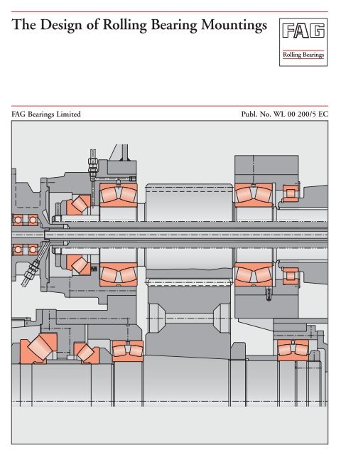
The FAG catalog The Design of Rolling Bearing Mountings contains excellent examples. For instance, the "Dryer roll bearings" example (ID LINK, section 4) clearly shows a self-aligning cylindrical roller bearing used as a floating bearing and a spherical roller bearing as the locating bearing.
Methods of Retention
Bearings must be securely held in place to function correctly. This can be done in several ways:

- Press/Interference Fits: The most common method. The bearing inner ring is pressed onto the shaft, and the outer ring is pressed into the housing.
- Retaining Rings (Circlips): As shown above, these are rings that sit in grooves on the shaft or in the housing bore to provide a hard stop, preventing axial movement. They are very common due to their simplicity and ease of assembly/disassembly.
- Adapter/Withdrawal Sleeves: For larger bearings, these tapered sleeves are used to clamp the bearing onto a cylindrical shaft, simplifying mounting and dismounting.
- Locknuts and Washers: A threaded nut and locking washer can be used on a shaft to clamp the inner ring of a bearing against a shoulder.
Conclusion
Today, we've walked through the complete process for selecting and integrating rolling bearings, a critical task for any mechanical designer. We've seen that the process is a logical workflow grounded in manufacturer data and fundamental engineering principles.
Key Takeaways:
- Bearing selection is an iterative process of validating life, not a direct calculation of size. You select a candidate and check if it meets the design requirements.
- The L10 life calculation is the industry standard. It relies on the bearing's Dynamic Load Rating (C) from a catalog and the Equivalent Dynamic Load (P) calculated from your application.
- The process is: calculate loads select a candidate bearing calculate its predicted life in hours compare to the required life for that application.
- Proper integration involves designing a locating/floating arrangement to manage thermal expansion and selecting appropriate retention methods like press fits, retaining rings, or locknuts.
Preview of the Next Lesson:
Now that we know how to support a rotating shaft with bearings, we need to protect those bearings. In our next lesson, we will focus on "Incorporate seals and retaining features (e.g., circlips, nuts) into a shaft assembly." We'll explore how to keep lubricants in and contaminants out, and take a closer look at the components used to hold our entire shaft stack-up together.