Hello! Welcome back to our module on Advanced Mechanical Components and Powertrains.
In our last lesson, we focused on selecting gears and calculating the ratios needed to transmit power and multiply torque. Now that we have a way to make things move, we need an equally robust way to hold them together. This brings us to one of the most fundamental and critical aspects of mechanical design.
Today's lesson will address the learning outcome: Design bolted joints with proper preload and safety factors. We will explore why a simple nut and bolt can create incredibly strong connections, how to quantify this strength through calculation, and how to ensure your design is safe against common failure modes. This is a core skill for any design engineer, especially in applications like automotive or industrial machinery where vibration and high loads are the norm.
1. The Power of Preload: The "Secret Sauce" of Bolted Joints
You've likely tightened countless bolts in your academic projects and as an intern. But what is actually happening within the materials when you apply that torque? The key concept is preload.
Preload is the tensile force created in a bolt as it is tightened, before any external service loads are applied. This tension in the bolt creates an equal and opposite compressive force on the parts being clamped together. This internal "clamping force" is what gives a bolted joint its strength and resistance to loosening.
To understand this intuitively, let's watch a short video from The Efficient Engineer that does an excellent job of visualizing the mechanics.
The Incredible Strength of Bolted Joints
This video provides a clear and concise explanation of what preload is and how it helps a joint resist both tension and shear loads.
Please watch from the beginning to 08:32. Pay close attention to: How tightening stretches the bolt to create preload (00:00 - 01:46). How preload works in a tension joint to prevent separation (01:46 - 04:43). How preload works in a shear joint to create friction and prevent slip (04:43 - 08:32).
As you saw in the video, preload is crucial for two main reasons:
- In Tension Joints: When an external force tries to pull the joint apart, that force must first overcome the compressive clamping force in the members before it can significantly add more tension to the bolt. This means the bolt is shielded from the full magnitude and fluctuation of the external load, dramatically improving its fatigue life.
- In Shear Joints: The clamping force creates a large frictional force between the faces of the joined parts. This friction resists the external shear load. In a well-designed "slip-resistant" joint, the bolt experiences no shear stress at all under normal service loads; it only maintains the clamping tension.
2. Sizing and Selection: How Much Preload and Which Bolt?
Now that we understand why preload is important, the practical engineering questions are: "How much preload do I need?" and "What bolt should I use to achieve it?"
Calculating Target Preload
The amount of preload is limited by the strength of the bolt material. A common engineering practice is to preload the bolt to a high percentage of its load-carrying capacity to maximize the benefits.
- For reusable or non-permanent joints, a target preload of 75% of the bolt's proof strength is often used.
- For permanent joints, this can be increased to 90% of the proof strength.
The proof strength () is the maximum stress a bolt can withstand without permanent deformation. If it's not specified, it can be conservatively estimated as 85% of the material's yield strength ().
The target preload force () is then calculated using the bolt's tensile stress area (), which accounts for the reduced cross-section at the threads:
Selecting the Bolt Grade
The strength of the bolt is defined by its material and heat treatment, which is standardized into property classes, or "grades." For ISO metric bolts, this is a system you've likely seen, such as "Class 8.8" or "10.9".
Complete Guide to Bolt Calculation- Size, Grade, Preload and Thumb rules
Understanding these numbers is key to selecting the right component. This video provides a very practical guide to interpreting bolt grades and selecting a factor of safety.
Please watch the following two segments: Bolt Grades (26:18 - 32:42): This section explains the ISO grading system (e.g., how to find tensile and yield strength from '10.9'), discusses common grades, and explains the difference between proof, yield, and tensile strength. Factor of Safety (32:42 - 34:10): This part provides practical guidance on choosing a factor of safety based on the application's criticality and loading conditions. Note the example of calculating the bolt size for a 20-ton load.
Key takeaways on bolt grades (e.g., Class 8.8):
- The first number () gives the Ultimate Tensile Strength (UTS) in MPa. So, .
- The first number () the second number () gives the Yield Strength in MPa. So, .
Applying Preload with Torque
The most common way to apply preload is by controlling the tightening torque with a torque wrench. The relationship is approximated by the formula:
Where:
- is the required torque.
- is the torque coefficient or "nut factor" (typically ~0.2 for standard zinc-plated bolts, but varies with lubrication and surface finish).
- is the nominal bolt diameter.
- is the target preload force.
It's important to remember that this method is notoriously inaccurate (±25% or more) because much of the torque is consumed by friction. For critical applications, methods like measuring bolt elongation are used, but torque control is standard for general engineering.
3. Joint Analysis: The Spring Model and Safety Factors
To analyze how the joint behaves under an external load (), we model it as a system of springs. The bolt acts as a spring in tension, and the clamped members act as a stiffer set of springs in compression.
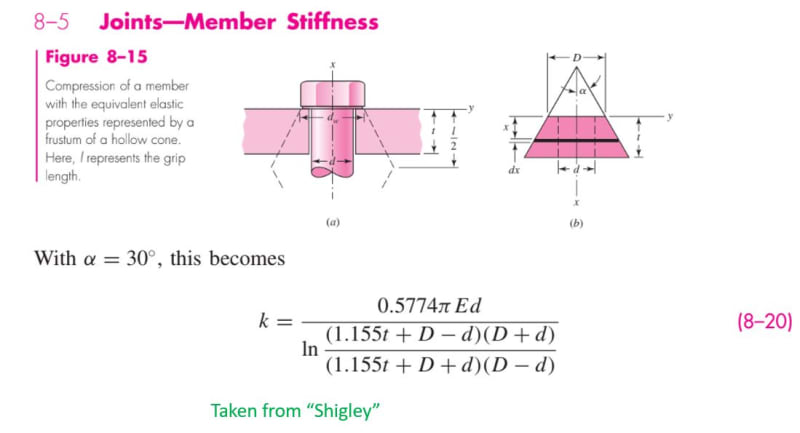
When an external tensile load is applied, it is shared between the bolt and the members. The portion of the load that further stretches the bolt, , is determined by the relative stiffness of the bolt () and the clamped members (). This relationship is defined by the joint constant, C:
The total tensile load on the bolt () is the sum of the initial preload and the portion of the external load it carries:
Since the members are typically much stiffer than the bolt (), the joint constant is a small number (e.g., 0.1 - 0.3). This confirms our earlier intuition: the bolt only sees a small fraction of the applied external load.
For a detailed walkthrough of the formulas for calculating stiffness, stresses, and safety factors, the following reference is an excellent resource.
This technical reference page from mechanicalc.com provides a comprehensive set of equations for a full bolted joint analysis. We'll use it as our guide for calculating safety factors.
Please review the following sections of the webpage. Focus on understanding the formulas and their purpose, not on memorizing them. Preload (Section: Preload): Quickly review the formulas for preload force and the torque equation. This will reinforce what we just covered. Bolt Load vs Applied Load (Section: Bolt Load vs Applied Load): This is crucial. Understand the joint constant 'C' and the equations for total bolt force (F_{b.t}) and the joint separation force (F_{sep}). Bolt Stresses (Section: Bolt Stresses): Look at how tensile, shear, and bending stresses are calculated, and how they combine into the von Mises stress. Thread Shear (Section: Thread Shear): Note that thread stripping is a distinct failure mode that must be checked.
Calculating Safety Factors
With this framework, we can now design a joint by checking it against key failure modes. For each mode, we calculate a factor of safety (). Your design is acceptable if all factors of safety are above a required minimum (e.g., 1.5, 2.0, or higher, depending on the application's criticality).
-
Safety Factor against Yielding (): This checks if the combined stresses in the bolt exceed the material's yield strength. It is the most common check.
- Calculate the total tensile stress and any shear stress .
- Combine them using the von Mises stress equation: . (Note: some conventions separate preload stress; the
mechanicalc.comapproach is common).
-
Safety Factor against Joint Separation (): This ensures the external load is not large enough to make the joint faces separate, which would cause the bolt to take the full load.
- The load required for separation is .
- For a safe joint, you want this value to be greater than 1, typically with a good margin.
-
Safety Factor against Thread Stripping (): This ensures the threads themselves don't shear off the bolt or out of the nut/tapped hole. This is critical when using a steel bolt in a softer material like aluminum.
- Calculations involve comparing the total bolt force to the shear strength of the cylindrical area of engaged threads. The formulas are in the
mechanicalc.comresource.
- Calculations involve comparing the total bolt force to the shear strength of the cylindrical area of engaged threads. The formulas are in the
Test your understanding!
You are designing a bolted joint for a cylinder head, a classic automotive application. The joint is subject to high cyclical tensile loads from combustion pressure. To improve the fatigue life of the bolts, would you want the joint to be "hard" (clamped members are very stiff compared to the bolt, ) or "soft" ()? Why?
Show answer
You would want a "hard" joint ().
The portion of the external load carried by the bolt is given by , where the joint constant is .
If the joint is hard, is very large compared to , making the value of very small. This means only a tiny fraction of the fluctuating combustion pressure load is felt by the bolt. The bolt maintains a nearly constant high tension (the preload), and is shielded from the stress fluctuations that cause fatigue failure.
4. The End Result: A Professional Analysis
In industry, especially for critical joints, these calculations are often performed using specialized software that adheres to standards like VDI 2230. The output is a formal report that documents all inputs, assumptions, and calculated safety factors.

This report perfectly illustrates how the concepts we've discussed—preload, member stiffness, external loads, and material properties—all come together to produce a verifiable and safe design.
Conclusion
Today, we've dissected the mechanics of bolted joints, moving from the foundational concept of preload to the detailed calculations required for a safe and robust design. As a mechanical engineer, mastering this topic is non-negotiable, as failed joints can have catastrophic consequences.
Key Takeaways:
- Preload is Essential: It creates a clamping force that protects the bolt from external loads and prevents loosening.
- The Joint is a Spring System: External loads are shared between the bolt and the clamped members based on their relative stiffness. A "hard" joint with stiff members and a relatively elastic bolt is desirable for fatigue resistance.
- Design is a Safety Check: A proper design involves selecting an appropriate bolt grade and preload, then verifying the design against multiple failure modes: yielding, joint separation, and thread stripping, ensuring all safety factors are met.
Preview of the Next Lesson:
We've now covered how to transmit power (gears) and how to fasten structures (bolts). The next logical step is to support the rotating components. In our next lesson, we will cover how to select and integrate standard bearings into an assembly based on load and life calculations. We'll explore different bearing types and learn how to use manufacturer catalogs to choose a bearing that will meet the life requirements of your design.